SERVICE AND ADJUSTMENTS
NOTE: If additional clearance is needed to get to adjustment bolt, move mower deck height to the lowest position.
After above adjustment is made, if the tractor still creeps forward or backward while motion control lever is in neutral position, follow these steps:
•Loosen the adjustment bolt.
•Move the motion control lever 1/4 to 1/2 inch in the direction it is trying to creep.
•Tighten adjustment bolt securely.
•Start engine and test.
•If tractor still creeps, repeat above steps until satisfied.
MOTION CONTROL | NEUTRAL |
LEVER | LOCK |
| GATE |
| ADJUSTMENT |
| BOLT |
Fig. 36
TO ADJUST MOTION CONTROL LEVER (See Fig. 37)
The motion control lever has been preset at the factory and adjustment should not be necessary.
If for any reason the motion control lever will not hold its position while at a selected speed, it may be adjusted at the friction pack located on the right side of transmission.
•Park tractor on level surface. Stop tractor by turning igni- tion key to “OFF” position, and engage parking brake.
•Adjust motion control lever by tightening adjustment locknut one half (1/2) turn.
NOTE: If for any reason the effort to move the motion control lever becomes too excessive, reverse the above adjustment procedure by loosening locknut 1/4 to 1/2 turn.
Road test tractor after adjustment and repeat procedure if necessary.
| FRICTION | |
| PACK | |
| ADJUSTMENT | |
6 | LOCKNUT | |
0152 | ||
| ||
Fig. 37 | 24 |
TO ADJUST STEERING WHEEL ALIGNMENT
If steering wheel crossbars are not horizontal (left to right) when wheels are positioned straight forward, remove steer- ing wheel and reassemble per instructions in the Assembly section of this manual.
FRONT WHEEL TOE-IN/CAMBER
Your new tractor front wheel
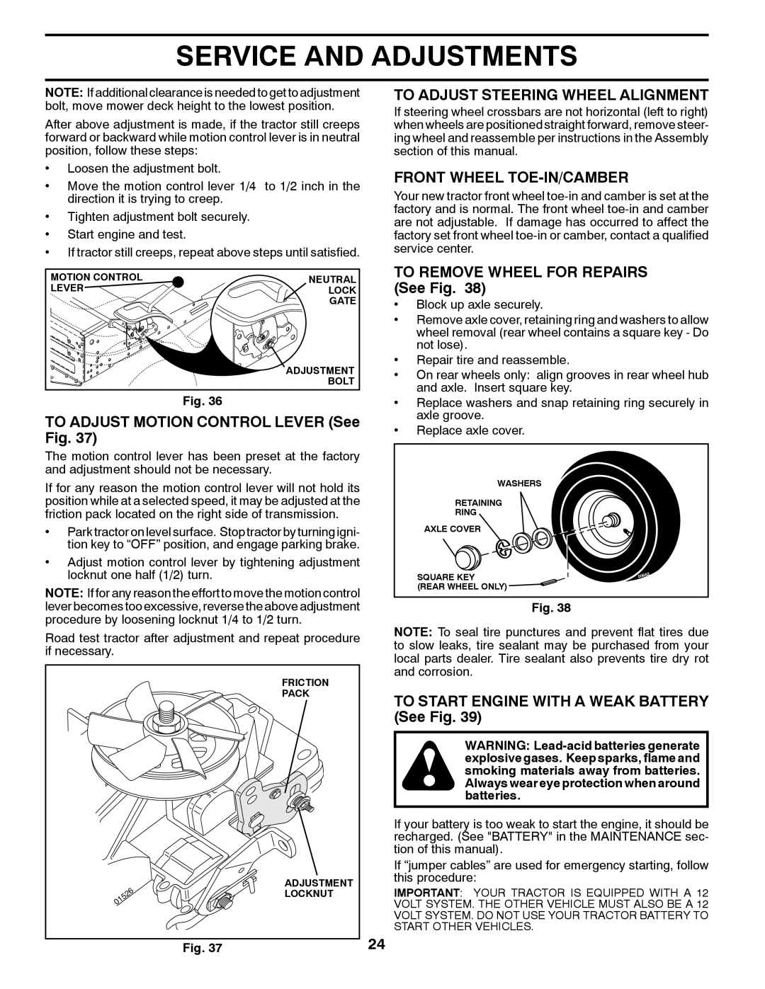
TO REMOVE WHEEL FOR REPAIRS (See Fig. 38)
•Block up axle securely.
•Remove axle cover, retaining ring and washers to allow wheel removal (rear wheel contains a square key - Do not lose).
•Repair tire and reassemble.
•On rear wheels only: align grooves in rear wheel hub and axle. Insert square key.
•Replace washers and snap retaining ring securely in axle groove.
•Replace axle cover.
WASHERS
RETAINING
RING
AXLE COVER
SQUARE KEY | 63 |
| 006 |
(REAR WHEEL ONLY)
Fig. 38
NOTE: To seal tire punctures and prevent flat tires due to slow leaks, tire sealant may be purchased from your local parts dealer. Tire sealant also prevents tire dry rot and corrosion.
TO START ENGINE WITH A WEAK BATTERY (See Fig. 39)
WARNING:
If your battery is too weak to start the engine, it should be recharged. (See "BATTERY" in the MAINTENANCE sec- tion of this manual).
If “jumper cables” are used for emergency starting, follow this procedure:
IMPORTANT: YOUR TRACTOR IS EQUIPPED WITH A 12 VOLT SYSTEM. THE OTHER VEHICLE MUST ALSO BE A 12 VOLT SYSTEM. DO NOT USE YOUR TRACTOR BATTERY TO START OTHER VEHICLES.