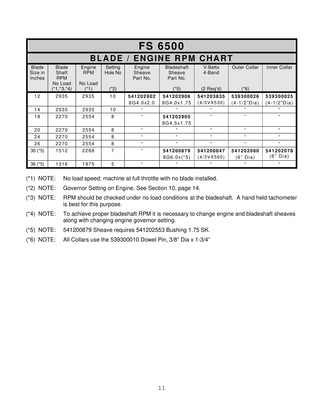
FS 6500, FS 3800 specifications
The Husqvarna FS 3800 and FS 6500 are both innovative and powerful floor saws designed for a variety of cutting applications in the construction industry. These machines are engineered to provide reliability, efficiency, and precision, catering to the needs of professional contractors.The Husqvarna FS 3800 is known for its compact design and high performance. This model features a robust 20 HP engine, ensuring powerful operation while maintaining fuel efficiency. The FS 3800 can handle a variety of cutting tasks, making it suitable for everything from small paving repairs to larger road construction projects. One of its standout features is the adjustable cutting depth, allowing users to achieve the exact cut depth required for their specific applications. Moreover, the machine offers excellent visibility for operators, thanks to its ergonomic design and well-placed controls.
On the other hand, the Husqvarna FS 6500 is designed for heavy-duty use and high performance. Equipped with a powerful 25 HP engine, it delivers exceptional cutting capabilities and reliability in challenging environments. The FS 6500 is capable of cutting through a wide range of materials, including concrete, asphalt, and bricks. Its user-friendly interface simplifies operation, making it accessible for operators of varying experience levels.
Both models incorporate advanced technologies to enhance performance and ease of use. They feature the SmartGuard system, which provides increased guidance during operation and improved safety features. This system minimizes the risk of kickback and ensures a smoother cutting experience. The machines are also equipped with an innovative vacuum system that helps reduce dust emissions, promoting a cleaner working environment.
In terms of portability, the FS 3800 and FS 6500 are equipped with durable foldable handles and transport wheels, enabling easy maneuverability on job sites. Both models are built with high-quality materials that ensure durability and longevity, even in the most demanding conditions.
In conclusion, the Husqvarna FS 3800 and FS 6500 stand out in the market for their robust performance, user-friendly features, and advanced technologies. These floor saws are ideal for professionals seeking reliable equipment to tackle a range of cutting tasks effectively. Their commitment to quality and innovation makes them essential tools for any contractor's toolkit.

