SERVICE AND ADJUSTMENTS
TRANSAXLE MOTION CONTROL LEVER NEUTRAL ADJUSTMENT(See Fig. 24)
The motion control lever has been preset at the factory and adjustment should not be necessary.
•Loosen adjustment bolt in front of the right rear wheel, and lightly tighten.
•Start engine and move motion control lever until tractor does not move forward or backward.
•Hold motion control lever in that position and turn engine off.
•While holding motion control lever in place, loosen the adjustment bolt.
•Move motion control lever to the neutral (N) (lock gate) position.
•Tighten adjustment bolt securely.
NOTE: If additional clearance is needed to get to adjustment bolt, move mower deck height to the lowest position.
After above adjustment is made, if the tractor still creeps forward or backward while motion control lever is in neutral position, follow these steps:
•Loosen the adjustment bolt.
•Move the motion control lever 1/4 to 1/2 inch in the direction it is trying to creep.
•Tighten adjustment bolt securely.
•Start engine and test.
•If tractor still creeps, repeat above steps until satis- fied.
MOTION CONTROL
LEVER
NEUTRAL LOCK GATE
ADJUSTMENT
BOLT
FIG. 24
TO ADJUST STEERING WHEEL ALIGNMENT
If steering wheel crossbars are not horizontal (left to right) when wheels are positioned straight forward, remove steer- ing wheel and reassemble per instructions in the Assembly section of this manual.
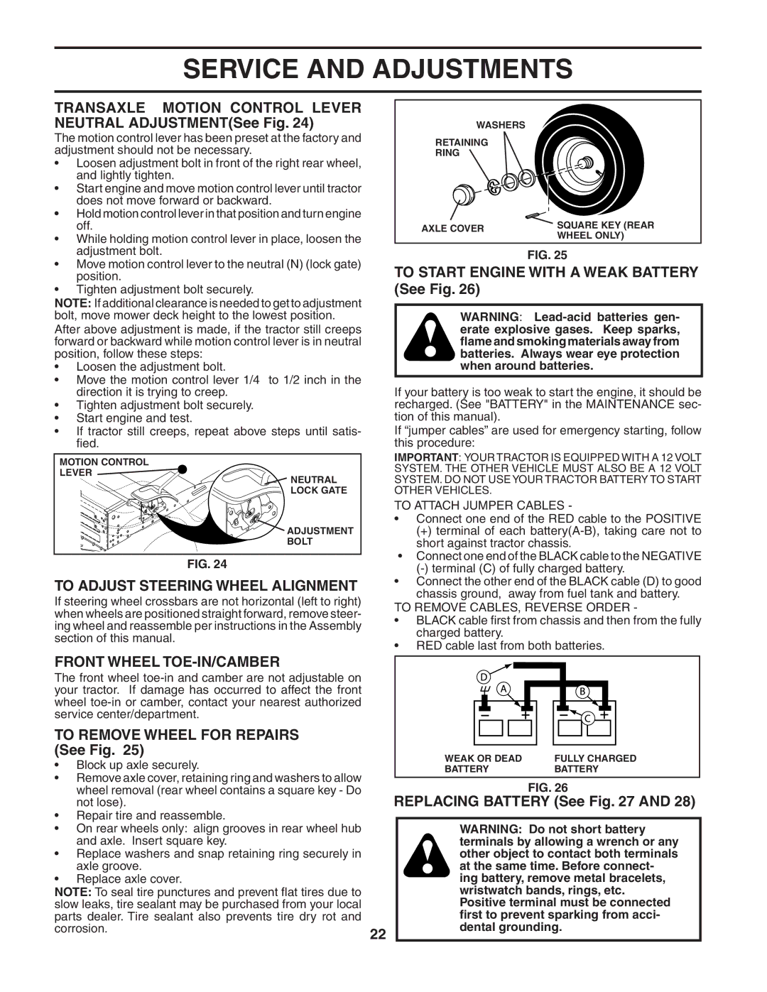
WASHERS
RETAINING
RING
AXLE COVER | SQUARE KEY (REAR | |
WHEEL ONLY) | ||
|
FIG. 25
TO START ENGINE WITH A WEAK BATTERY (See Fig. 26)
WARNING:
If your battery is too weak to start the engine, it should be recharged. (See "BATTERY" in the MAINTENANCE sec- tion of this manual).
If “jumper cables” are used for emergency starting, follow this procedure:
IMPORTANT: YOUR TRACTOR IS EQUIPPED WITH A 12 VOLT SYSTEM. THE OTHER VEHICLE MUST ALSO BE A 12 VOLT SYSTEM. DO NOT USE YOUR TRACTOR BATTERY TO START OTHER VEHICLES.
TO ATTACH JUMPER CABLES -
•Connect one end of the RED cable to the POSITIVE
(+)terminal of each
•Connect one end of the BLACK cable to the NEGATIVE
•Connect the other end of the BLACK cable (D) to good chassis ground, away from fuel tank and battery.
TO REMOVE CABLES, REVERSE ORDER -
•BLACK cable first from chassis and then from the fully charged battery.
•RED cable last from both batteries.
FRONT WHEEL |
|
| |
The front wheel |
|
| |
your tractor. If damage has occurred to affect the front |
|
| |
wheel |
|
| |
service center/department. |
|
| |
TO REMOVE WHEEL FOR REPAIRS |
|
| |
(See Fig. 25) | WEAK OR DEAD | FULLY CHARGED | |
• Block up axle securely. | |||
BATTERY | BATTERY |
•Remove axle cover, retaining ring and washers to allow
| wheel removal (rear wheel contains a square key - Do |
|
| FIG. 26 |
| not lose). |
| REPLACING BATTERY (See Fig. 27 AND 28) | |
• Repair tire and reassemble. |
|
|
| |
• | On rear wheels only: align grooves in rear wheel hub |
|
| WARNING: Do not short battery |
| and axle. Insert square key. |
|
| terminals by allowing a wrench or any |
• Replace washers and snap retaining ring securely in |
|
| other object to contact both terminals | |
| axle groove. |
|
| at the same time. Before connect- |
• | Replace axle cover. |
|
| ing battery, remove metal bracelets, |
NOTE: To seal tire punctures and prevent flat tires due to |
|
| wristwatch bands, rings, etc. | |
slow leaks, tire sealant may be purchased from your local |
|
| Positive terminal must be connected | |
parts dealer. Tire sealant also prevents tire dry rot and |
|
| first to prevent sparking from acci- | |
corrosion. | 22 |
| dental grounding. | |
|
|
|
| |