ASSEMBLY / PRE-OPERATION
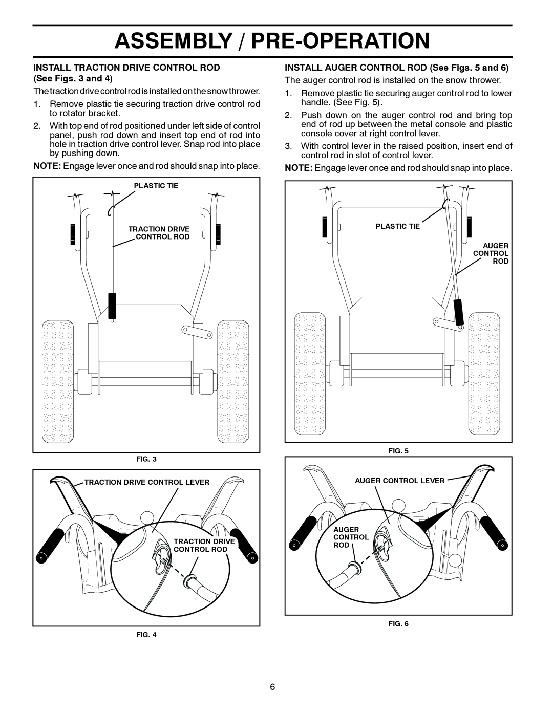
INSTALL TRACTION DRIVE CONTROL ROD (See Figs. 3 and 4)
The traction drive control rod is installed on the snow thrower.
1.Remove plastic tie securing traction drive control rod to rotator bracket.
2.With top end of rod positioned under left side of control panel, push rod down and insert top end of rod into hole in traction drive control lever. Snap rod into place by pushing down.
NOTE: Engage lever once and rod should snap into place.
PLASTIC TIE |
TRACTION DRIVE |
CONTROL ROD |
FIG. 3
TRACTION DRIVE CONTROL LEVER |
TRACTION DRIVE |
CONTROL ROD |
FIG. 4
INSTALL AUGER CONTROL ROD (See Figs. 5 and 6)
The auger control rod is installed on the snow thrower.
1.Remove plastic tie securing auger control rod to lower handle. (See Fig. 5).
2.Push down on the auger control rod and bring top end of rod up between the metal console and plastic console cover at right control lever.
3.With control lever in the raised position, insert end of control rod in slot of control lever.
NOTE: Engage lever once and rod should snap into place.
PLASTIC TIE |
AUGER |
CONTROL |
ROD |
FIG. 5
AUGER CONTROL LEVER |
AUGER |
CONTROL |
ROD |
FIG. 6
6