SERVICE AND ADJUSTMENTS
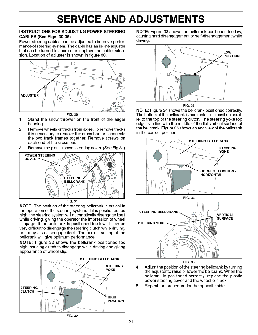
INSTRUCTIONS FOR ADJUSTING POWER STEERING CABLES (See Figs. 30-35)
Power steering cables can be adjusted to improve perfor- mance of steering system. The cable has an
ADJUSTER |
FIG. 30
1.Stand the snow thrower on the front of the auger housing.
2.Remove wheels or tracks from axles. To remove tracks it is necessary to remove the cross bar that connects the two track frames together. Remove screws on each end of the cross bar.
3.Remove the plastic power steering cover. (See Fig.31)
POWER STEERING
COVER ![]()
![]()
![]()
![]()
STEERING
BELLCRANK ![]()
FIG. 31
NOTE: Figure 33 shows the bellcrank positioned too low, causing hard disengagement or ![]()
LOW
POSITION
FIG. 33
NOTE: Figure 34 shows the bellcrank positioned correctly. The bottom of the bellcrank is horizontal, in a position paral- lel to the top of the steering clutch. The steering yoke top edge is in line with the middle of the flat vertical surface of the bellcrank. Figure 35 shows an end view of the bellcrank in the correct position.
STEERING BELLCRANK
STEERING
YOKE
![]()
![]() CORRECT POSITION -
CORRECT POSITION -
HORIZONTAL
FIG. 34
NOTE: The position of the steering bellcrank is critical in the operation of the steering system. If it is positioned too high, the steering system will automatically disengage itself while driving, giving the operator the impression of wheel slippage. If the bellcrank is positioned too low, it may be very difficult to disengage the steering clutch while driving, or it may also disengage itself. The correct setting of the bellcrank will give optimum performance.
NOTE: Figure 32 shows the bellcrank positioned too high, causing clutch to disengage while driving and giving appearance of wheel slip.
STEERING BELLCRANK
STEERING YOKE
VERTICAL SURFACE
STEERING BELLCRANK
STEERING
YOKE
STEERING CLUTCH
HIGH POSITION
FIG. 32
FIG. 35
4.Adjust the position of the steering bellcrank by turning the adjuster to raise or lower the bellcrank. When the bellcrank is positioned correctly, replace the plastic power steering cover and the wheel or track.
5.Repeat the procedure for the opposite side.
21
