Grass catcher
Fig.
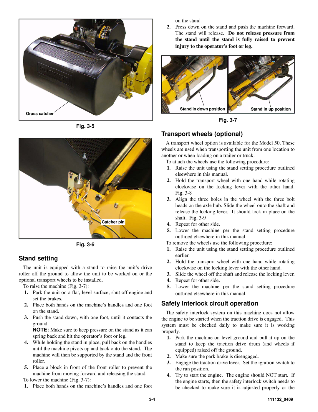
![]() Catcher pin
Catcher pin
Fig.
Stand setting
The unit is equipped with a stand to raise the unit’s drive roller off the ground to allow the unit to be worked on or the optional transport wheels to be installed.
To raise the machine (Fig.
1.Park the unit on a flat, level surface, shut off engine and set the brakes.
2.Place both hands on the machine’s handles and one foot on the stand.
3.Push the stand down, with one foot, until it contacts the ground.
NOTE: Make sure to keep pressure on the stand as it can spring back and hit the operator’s foot or leg.
4.While holding the stand in place, pull back on the handles until the machine pivots up and back onto the stand. The machine will then be supported by the stand and the front roller.
5.Place a block in front of the front roller to prevent the
machine from moving forward and releasing the stand. To lower the machine (Fig.
1.Place both hands on the machine’s handles and one foot
on the stand.
2.Press down on the stand and push the machine forward. The stand will release. Do not release pressure from the stand until the stand is fully raised to prevent injury to the operator’s foot or leg.
|
|
|
|
| Stand in down position |
| Stand in up position |
|
|
|
|
Fig.
Transport wheels (optional)
A transport wheel option is available for the Model 50. These wheels are used when transporting the unit from one location to another or when loading on a trailer or truck.
To attach the wheels use the following procedure:
1.Raise the unit using the stand setting procedure outlined elsewhere in this manual.
2.Hold the transport wheel with one hand while rotating clockwise on the locking lever with the other hand. Fig.
3.Align the three holes in the wheel with the three bolt heads on the axle hub. Slide the wheel onto the shaft and release the locking lever. It should lock in place on the shaft. Fig.
4.Repeat for other side.
5.Lower the machine per the stand setting procedure outlined elsewhere in this manual.
To remove the wheels use the following procedure:
1.Raise the unit using the stand setting procedure outlined earlier.
2.Hold the transport wheel with one hand while rotating clockwise on the locking lever with the other hand.
3.Slide the wheel off the shaft and release the locking lever.
4.Repeat for other side.
5.Lower the machine per the stand setting procedure outlined elsewhere in this manual.
Safety Interlock circuit operation
The safety interlock system on this machine does not allow the engine to be started when the traction drive is engaged. This system must be checked daily to make sure it is working properly.
1.Park the machine on level ground and pull it up on the stand to keep the traction drive drum (and wheels if equipped) raised off the ground.
2.Make sure the park brake is disengaged.
3.Engage the traction drive lever. Set the ignition switch to the run position.
4.Try to start the engine. The engine should NOT start. If the engine starts, then the safety interlock switch needs to be checked to make sure it is adjusted properly or the
111132_0409 |