TROUBLESHOOTING
Hydraulic Energy Regulated Output (H.E.R.O.) is more than just our name, it is the bases for the operation of the pump. It is the regulation or control, of hydraulic energy, which allows the equipment to build and then deliver or have an output of pressure. Once you have a basic understanding of the operation of the equipment and the effect created in one area and how it will effect operation in another area, you will be better able to diagnose and make repairs.
All H.E.R.O. hydrapulse membrane pumps are made up of two (2) distinct pumps. The first, and most important pump is the hydraulic pump. The hydraulic system is made up of two valves, the hydraulic intake valve (ref# 59) and the hydraulic outgo valve, known as the hydraulic pressure control valve (ref# 70). The second pump is known as the paint or material pump. The paint system is made up of two basic valves, the paint intake valve assembly (ref#
At the center of these two pumps is the hydrapulse membrane. The hydrapulse membrane is a flexible nylon disc which transfers the energy (pressure) created by the hydraulic pump, to create energy (pressure) in the paint pump. The function of the hydrapulse membrane is to create a barrier between the hydraulic oil and the spray material and transfer the energy created.
To fully understand and trouble shoot a H.E.R.O. pump, always keep in mind that "for every action, there is an opposite or corresponding
For correct operation to begin, the hydraulic system must be fully primed and all air must be removed
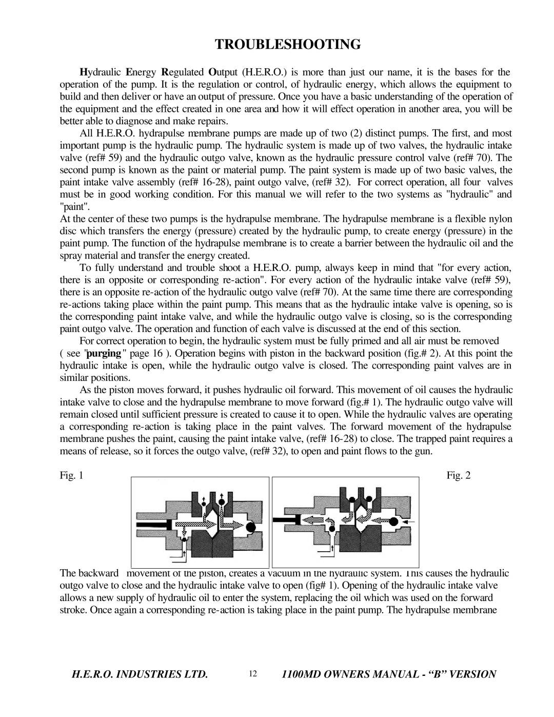
( see "purging " page 16 ). Operation begins with piston in the backward position (fig.# 2). At this point the hydraulic intake is open, while the hydraulic outgo valve is closed. The corresponding paint valves are in similar positions.
As the piston moves forward, it pushes hydraulic oil forward. This movement of oil causes the hydraulic intake valve to close and the hydrapulse membrane to move forward (fig.# 1). The hydraulic outgo valve will remain closed until sufficient pressure is created to cause it to open. While the hydraulic valves are operating a corresponding
Fig. 1 | Fig. 2 |
The backward movement of the piston, creates a vacuum in the hydraulic system. This causes the hydraulic outgo valve to close and the hydraulic intake valve to open (fig# 1). Opening of the hydraulic intake valve allows a new supply of hydraulic oil to enter the system, replacing the oil which was used on the forward stroke. Once again a corresponding
H.E.R.O. INDUSTRIES LTD. | 12 | 1100MD OWNERS MANUAL - “B” VERSION |