Step 3. Setting the SCSI ID, termination, and parity
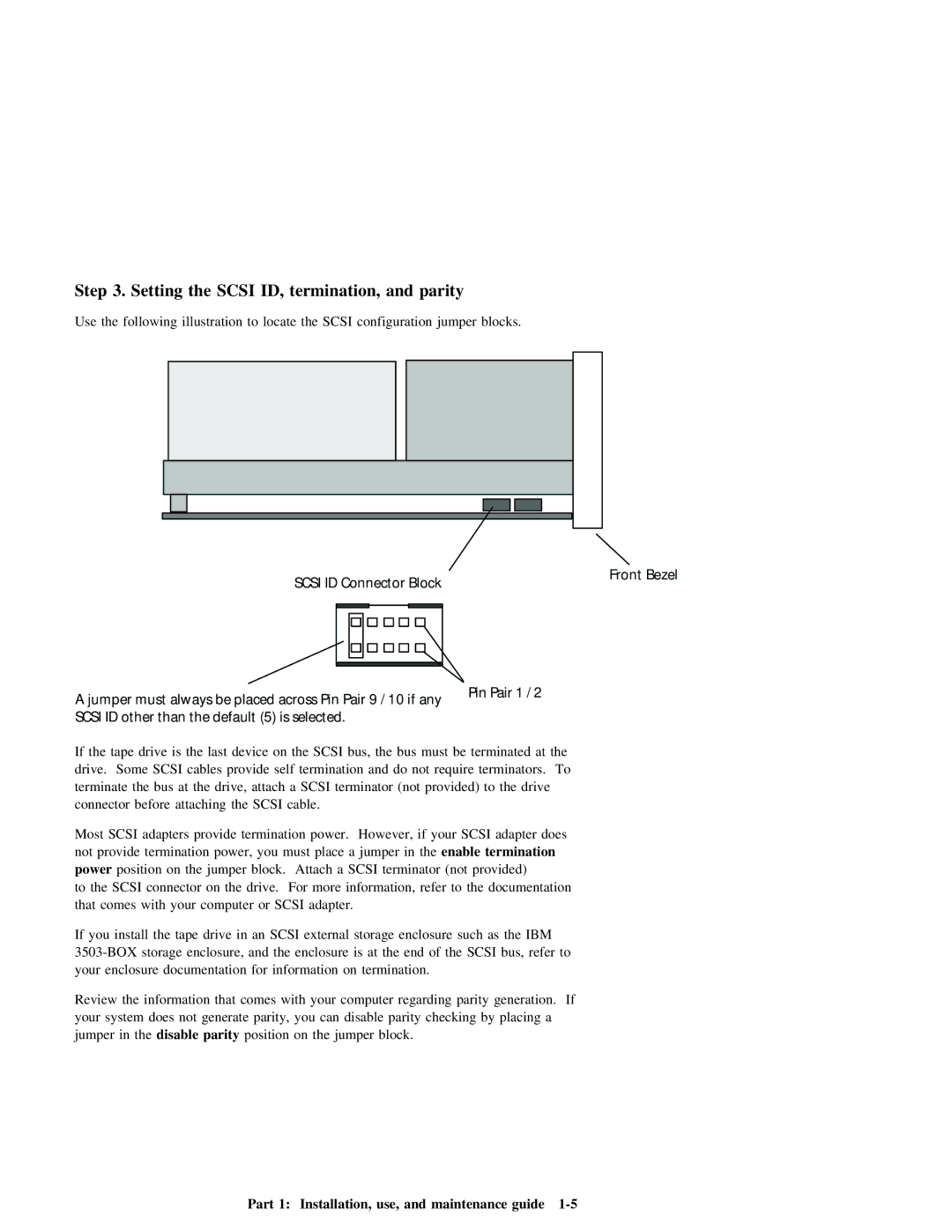
Use the following illustration to locate the SCSI configuration jumper blocks.
SCSI ID Connector Block
Front Bezel
A jumper must always be placed across Pin Pair 9 / 10 if any |
| Pin Pair 1 / 2 |
| |||||||||||||||||||||||
|
|
|
|
|
| |||||||||||||||||||||
SCSI ID other than the default (5) is selected. |
|
|
|
|
|
|
|
|
|
| ||||||||||||||||
If | the | tape | drive | is | the | last | device |
| on | the | SCSI | bus, | the | bus | must | be | terminated at the | |||||||||
drive. Some | SCSI | cables | provide self | termination | and | do | not require | terminators. To |
| |||||||||||||||||
terminate | the | bus | at |
| the | drive, | attach |
| a | SCSI | terminator | (not provided) | to | the | drive | |||||||||||
connector | before |
| attaching | the | SCSI | cable. |
|
|
|
|
|
|
|
|
|
|
|
|
| |||||||
Most | SCSI | adapters | provide | termination | power. However, | if | your | SCSI | adapter | does |
|
| ||||||||||||||
not | provide |
| termination |
| power, | you | must | place | a | jumper | in | the enable | termination |
|
| |||||||||||
power | position |
| on | the |
| jumper | block. | Attach | a | SCSI | terminator | (not | provided) |
|
|
| ||||||||||
to | the | SCSI | connector |
| on | the | drive. | For | more information, | refer | to | the | documentation |
| ||||||||||||
that | comes |
| with | your |
| computer | or | SCSI | adapter. |
|
|
|
|
|
|
|
|
|
| |||||||
If | you | install | the | tape | drive | in | an | SCSI | external | storage | enclosure | such | as | the | IBM | |||||||||||
storage | enclosure, | and | the | enclosure | is | at the end of the | SCSI bus, | refer | to | |||||||||||||||||
your | enclosure |
| documentation for information on termination. |
|
|
|
|
|
|
|
|
| ||||||||||||||
Review | the |
| information |
| that | comes | with | your | computer | regarding | parity | generation. | If |
| ||||||||||||
your | system | does | not | generate | parity, |
| you | can | disable | parity | checking | by | placing a |
| ||||||||||||
jumper | in | the | disable | parity | position | on |
| the | jumper block. |
|
|
|
|
|
|
| ||||||||||