MS-7236 Mainboard
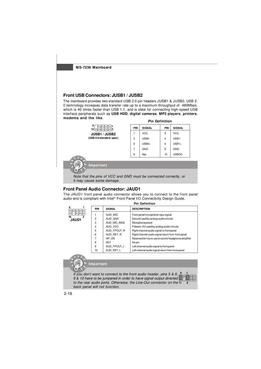
Front USB Connectors: JUSB1 / JUSB2
The mainboard provides two standard USB 2.0 pin headers JUSB1 & JUSB2. USB 2. 0 technology increases data transfer rate up to a maximum throughput of 480Mbps, which is 40 times faster than USB 1.1, and is ideal for connecting
|
|
| Pin Definition |
| ||
9 | 1 | PIN | SIGNAL | PIN | SIGNAL | |
10 | 2 | |||||
|
|
|
| |||
JUSB1 / JUSB2 | 1 | VCC | 2 | VCC | ||
(USB 2.0/standard spec) | 3 | USB0- | 4 | USB1- | ||
|
| 5 | USB0+ | 6 | USB1+ | |
|
| 7 | GND | 8 | GND | |
|
| 9 | Key | 10 | USBOC | |
Important
Note that the pins of VCC and GND must be connected correctly, or it may cause some damage.
Front Panel Audio Connector: JAUD1
The JAUD1 front panel audio connector allows you to connect to the front panel audio and is compliant with Intel® Front Panel I/O Connectivity Design Guide.
9 1
10 2
JAUD1
|
| Pin Definition |
PIN | SIGNAL | DESCRIPTION |
1 | AUD_MIC | Front panel microphone input signal |
2 | AUD_GND | Ground used by analog audio circuits |
3 | AUD_MIC_BIAS | Microphonepower |
4 | AUD_VCC | Filtered +5V used by analog audio circuits |
5 | AUD_FPOUT_R | Right channel audio signal to front panel |
6 | AUD_RET_R | Right channel audio signal return from front panel |
7 | HP_ON | Reserved for future use to control headphone amplifier |
8 | KEY | No pin |
9 | AUD_FPOUT_L | Left channel audio signal to front panel |
10 | AUD_RET_L | Left channel audio signal return from front panel |
Important
If you don’t want to connect to the front audio header, pins 5 & 6, 9 9 & 10 have to be jumpered in order to have signal output directed to the rear audio ports. Otherwise, the
5
6