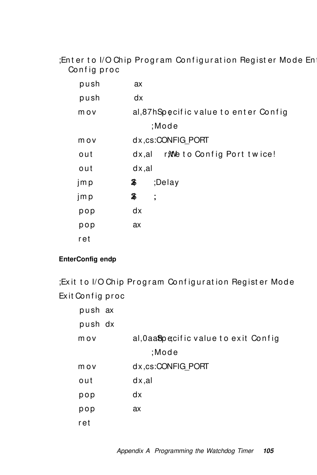
PCM-6890B
FCC STATEMENT
Acknowledgements
Copyright Notice
A Message to the Customer
AAEON Customer Services
Technical Support
Product Warranty
Packing list
Dear Customer
Chapter 1 General Information
Chapter 2 Installaion
Contents
Chapter 4 C&T 69000 Flat Panel/CRT controller
Chapter 3 Award BIOS Setup
Display Drivers and Utilities
Appendix B Installing PC/104 Modules
Chapter 5 Ethernet Software Configuration
Chapter 6 Audio Setup
Timer
Sections include Board specifications Layout and dimensions
General Information
This chapter gives background informa- tion on the mainboard
Highly integrated multi-media SBC
Introduction
C&T69000 LCD controller supports 36-bit TFT Panels
Features
Supports DiskOnChip SSD up to 288MB PC/104 expansion connector
Supports Intel Pentium III, Celeron CPUs, and compatible CPUs
Standard SBC Functions
Specifications
PCI Sound Interface
Flat Panel/CRT Interface
Ethernet interface
Mechanical and environmental
Typical power requirement +5V@4A
SSD Interface
Expansion Slots
Chapter 1 General Information
Board layout
8 PCM-6890B User Manual
Board dimensions
AAEON PCM-6890B Rev B1.0 Mechanical Drawing UNIT mm
C H A P T E R
Installation
Label
Jumpers and connectors
Function
Label
CPU fan power connector
Function
12 PCM-6890B User Manual
Locating jumpers & connectors
Setting jumpers
14 PCM-6890B User Manual
CPU installing and upgrading
Supplementary information about DIMM
Installing DRAM DIMMs
Memory Installation Procedures
System Memory
16 PCM-6890B User Manual
Cache memory
Clear CMOS J1
System temperature thermal sensor J2
MicAmp JP1
+12V
COM3/COM4 RI pin voltage select J3, J4
COM3 RI pin setting J4
COM4 RI pin setting J3
Speaker out
ATX Soft-Power Switch connector J6
Audio output select J5
Line out
RS-485
COM2 RS-232/422/485 select J10, J7
RS-232
RS-422
Chapter 2 Installation
LCD clock signal select J8
LCD driving voltage select J9
LCD clock signal select J8
ATX power connector CN9
Power connectors CN9, CN1
CPU fan power connector CN1
CD Audio connector CN4
USB connector CN3
Connecting the hard drive
IDE hard drive connector CN6
Signal
IDE hard drive connector CN6
Signal
Speaker
Front panel connector CN7
LED interface
1 Vcc 2 NC 3 IrRx 4 GND 5 IrTx
IrDA connector CN8
VGA display connector CN12
Display connectors CN10, CN12
LCD connector CN10
Keyboard and mouse connector CN11
1 KB DATA 2 GND 3 MS DATA 4 N/C 5 KB CLOCK 6 Vcc 7 MS CLOCK 8 N/C
Audio connector CN13
Parallel port connector table CN14
Parallel port connector CN14
Parallel port IRQ
100Base-T Ethernet connector CN15
Signal
Signal
SIGNAL
Serial ports CN16
COM 1-4 RS-232/422/485 serial ports CN16
SIGNAL
Connecting the floppy drive
Floppy drive connector CN17
Signal
Floppy drive connector CN17
Signal
default
SW1 2~3 DOC address select
Ethernet active signal LED J14J15
Ethernet LED signal connectors LED2
Ethernet link signal LED
DiskOnChip socket U18
Configure DOC as a boot device
DiskOnChip DOC 2000 Installation
This chapter describes how to configure the BIOS for the PCM-6890B
Award BIOS Setup
Starting setup
These keys helps you navigate in Setup
Setup keys
Getting help
In Case of Problems
Main setup Menu
46 PCM-6890B User Manual
Chapter 3 Award BIOS Setup
Standard CMOS setup
If you do not want to select drive type AUTO, other methods of
NOTE We recommend that you select type AUTO for all drives
selecting the drive type are available
LCD & CRT
Drive A Drive B
Pannel
Base Memory
Other Memory
Extended Memory
52 PCM-6890B User Manual
Chapter 3 Award BIOS Setup
BIOS features setup
CPU L2 Cache ECC Checking
Quick Power On Self Test
Virus Warning
CPU Internal Cache/External Cache
Swap Floppy Drive
Boot Sequence
Boot Up Floppy Seek
Boot Up NumLock Status
56 PCM-6890B User Manual
Shadow
Chapter 3 Award BIOS Setup
CHIPSET features setup
58 PCM-6890B User Manual
SDRAM RAS-to-CAS Delay
SDRAM RAS Precharge Time
SDRAM CAS Latency Time
8/16 Bit I/O Recovery Time
DRAM Data Integrity Mode
System BIOS Cacheable
Video BIOS Cacheable
Auto Detect DIMM/PCI Clk
Delayed Transaction
Memory Hole at 15M-16M
Passive Release
Chapter 3 Award BIOS Setup
Power management setup
Power Management
Determines the manner in which the monitor is blanked
Throttle Duty Cycle
Standby Mode
Suspend Mode
HDD Power Down
IRQ8 Break Event From Suspend
Reload Global Timer Events
IRQ3-7, 9-15, NMI Primary IDE Primary IDE Floppy Disk Serial Port
Parallel Port
66 PCM-6890B User Manual
PNP/PCI configuration setup
Resources Controlled By
PNP OS Installed
Reset Configuration Data
Chapter 3 Award BIOS Setup
Used Mem Length
PCI IRQ Activated by
Assign IRQ for VGA
Used Mem base addr
Load BIOS defaults/Load setup defaults
70 PCM-6890B User Manual
Integrated peripherals setup
Select Enabled only if your hard drives support block mode
Serial Port 4 Use IRQ
Onboard Serial Port Serial Port 3 Use IRQ Onboard Serial Port
Chapter 3 Award BIOS Setup
Supervisor/User password setting
CONFIRM PASSWORD
ENTER PASSWORD
Chapter 3 Award BIOS Setup
IDE HDD auto detection
76 PCM-6890B User Manual
Save & exit setup
This chapter provides information about Driver types and installation
Flat Panel/CRT Controller Display Drivers and Utilities
Software drivers
Hardware configuration
Before you begin
Necessary prerequisites
Windows
Driver installation
Chapter 4 Driver Installation
82 PCM-6890B User Manual
model name the model number of your product
Chapter 4 Driver Installation
2. Place the Supporting CD-ROM in your CD-ROM drive
cd-rom the drive letter of your CD-ROM drive
84 PCM-6890B User Manual
Chapter 4 Driver Installation
3. Once the installation is complete, the Advanced display Properties
window will reappear. Show as figure
86 PCM-6890B User Manual
Chapter 4 Driver Installation
88 PCM-6890B User Manual
Driver installation
Windows
Windows subdirectory
OS/2
90 PCM-6890B User Manual
Driver installation
Windows NT
Windows NT
Driver installation
92 PCM-6890B User Manual
Ethernet Software Configuration
Ethernet software configuration
Audio Setup
Introduction
Setting Up in Windows
9 6 PCM-6890B User Manual
disk when you install the joystick or MIDI device
Installing the Drivers and the Application
· ESS Gameport Joystick · SB Audio PCI 64V Legacy Device
Installing the Audio Drivers
Setting Up in NT4.0
Driver installation
100 PCM-6890B User Manual
Programming the Watchdog Timer
Watchdog timer
Programming the watchdog timer
Configuration register
How to set the watchdog timer
Example
DATAPORT dw 3f1h
EnterConfig endp
SelectDevice endp
ExitConfig endp
106 PCM-6890B User Manual
W977Write PROC
108 PCM-6890B User Manual
Installing PC/104 Modules
PCM-3660
Installing PC/104 modules
PCM-3115B
PCM-3610
Appendix B Installing PC/104 Modules
PC/104 Module Mounting Diagram
PC/104 module dimenstions inches ±5%
112 PCM-6890B User Manual