Product Description
This document describes the hardware and software installation of the
IBM* Personal Computer AT* or AT compatible computer. Both controllers' Winchester interface conform to ST506/ST412 specifications. The
Installation
This section briefly describes the installation of the controller board. Do NOT use the
compatible, or XT* floppy controller in the same system. Removal of the extra floppy controller is necessary for proper operation of the
A minor incompatibility exists between the
CAUTION
Handle the controller board by the ends of the board. Some of the chips are static sensitive and damage may occur if the board is incorrectly handled.
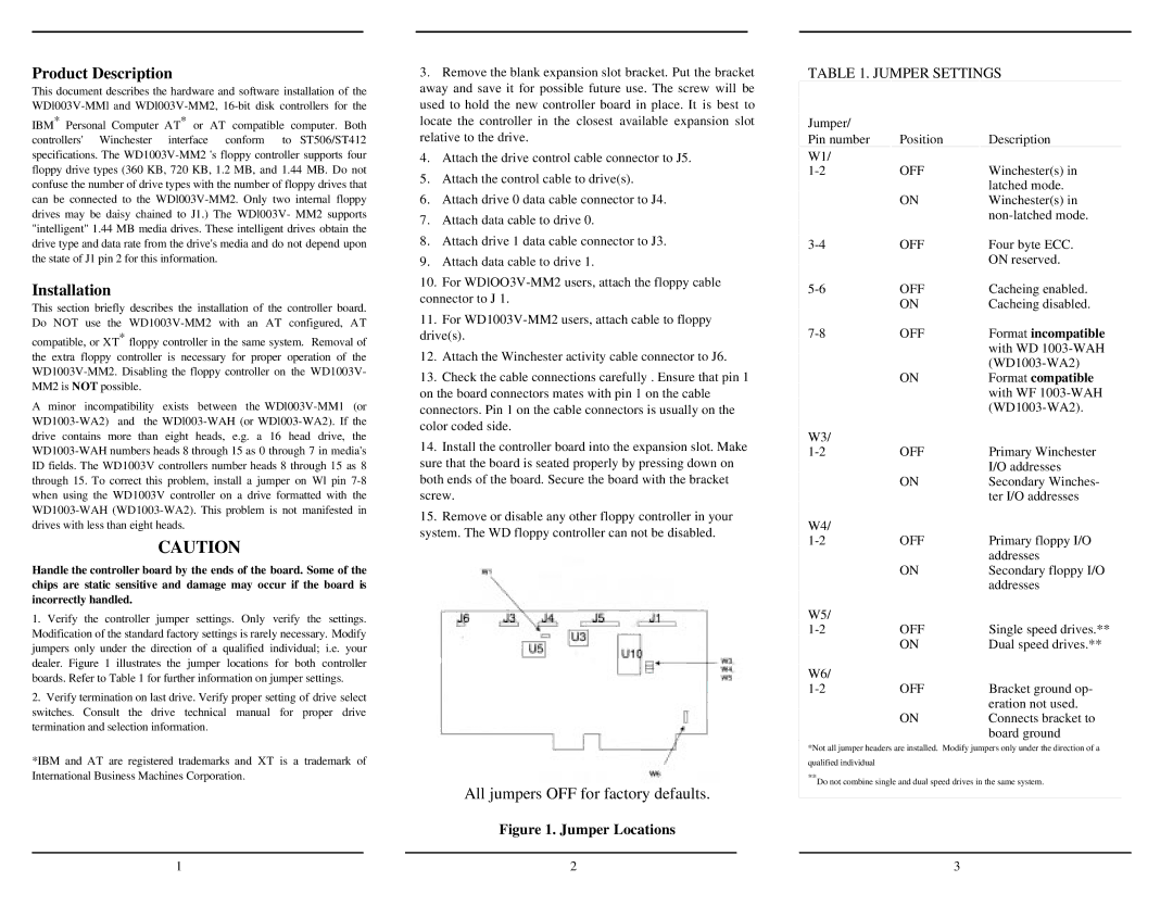
1.Verify the controller jumper settings. Only verify the settings. Modification of the standard factory settings is rarely necessary. Modify jumpers only under the direction of a qualified individual; i.e. your dealer. Figure 1 illustrates the jumper locations for both controller boards. Refer to Table 1 for further information on jumper settings.
2.Verify termination on last drive. Verify proper setting of drive select switches. Consult the drive technical manual for proper drive termination and selection information.
*IBM and AT are registered trademarks and XT is a trademark of International Business Machines Corporation.
3.Remove the blank expansion slot bracket. Put the bracket away and save it for possible future use. The screw will be used to hold the new controller board in place. It is best to locate the controller in the closest available expansion slot relative to the drive.
4.Attach the drive control cable connector to J5.
5.Attach the control cable to drive(s).
6.Attach drive 0 data cable connector to J4.
7.Attach data cable to drive 0.
8.Attach drive 1 data cable connector to J3.
9.Attach data cable to drive 1.
10.For
11.For
12.Attach the Winchester activity cable connector to J6.
13.Check the cable connections carefully . Ensure that pin 1 on the board connectors mates with pin 1 on the cable connectors. Pin 1 on the cable connectors is usually on the color coded side.
14.Install the controller board into the expansion slot. Make sure that the board is seated properly by pressing down on both ends of the board. Secure the board with the bracket screw.
15.Remove or disable any other floppy controller in your system. The WD floppy controller can not be disabled.
All jumpers OFF for factory defaults.
Figure 1. Jumper Locations
TABLE 1. JUMPER SETTINGS
Jumper/ |
|
|
Pin number | Position | Description |
W1/ |
|
|
OFF | Winchester(s) in | |
|
| latched mode. |
| ON | Winchester(s) in |
|
| |
OFF | Four byte ECC. | |
|
| ON reserved. |
OFF | Cacheing enabled. | |
| ON | Cacheing disabled. |
OFF | Format incompatible | |
|
| with WD |
|
| |
| ON | Format compatible |
|
| with WF |
|
| |
W3/ |
|
|
OFF | Primary Winchester | |
|
| I/O addresses |
| ON | Secondary Winches- |
|
| ter I/O addresses |
W4/ |
|
|
OFF | Primary floppy I/O | |
|
| addresses |
| ON | Secondary floppy I/O |
|
| addresses |
W5/ |
|
|
OFF | Single speed drives.** | |
| ON | Dual speed drives.** |
W6/ |
|
|
OFF | Bracket ground op- | |
|
| eration not used. |
| ON | Connects bracket to |
|
| board ground |
*Not all jumper headers are installed. Modify jumpers only under the direction of a
qualified individual
**Do not combine single and dual speed drives in the same system.
1 | 2 | 3 |