SECTION 5 CIRCUIT DESCRIPTION

5-1 RECEIVER CIRCUITS

5-1-1 ANTENNA SWITCHING CIRCUIT (PA UNIT)

The antenna switching circuit toggles the receive (RX) line and transmit (TX) line.

The received signals from the antenna are passed through the low-pass filter (ANT UNIT; L801, L802, C802, C803, C807) and antenna switch (D701, D704, D706).

While transmitting, the voltage on the T5V line is applied to D701, D704 and D706, and these are ON. Thus the TX line is connected to the antenna. Simultaneously, the RX line is connected to the ground (GND) to prevent transmit signal entering.

While receiving, no voltage is applied to the D701, D704 and D706, and these are OFF. Thus the TX line and the antenna are disconnected to prevent received signals entering. Simultaneously, the RX line is disconnected from the GND and the received signals are passed through the low-pass filter (L712, L714, C750, C751). The fi ltered signals are applied to the RF circuits.

5-1-2 RF CIRCUITS (MAIN UNIT)

RF circuits filter and amplify the received signals within the frequency coverage.

The received signals from the antenna switching circuit are passed though the two-staged bandpass filter (BPF; D19, D24, L7, L8, C22, C25, C27–C29, C369) to fi lter-out unwanted signals, and the fi ltered signals are applied to the RF amplifi er (Q5). The amplifi ed received signals are then applied to the 1st mixer (Q6) via another BPF (L47–L49, C19, C40, C437–C439, C443).

5-1-3 1st IF CIRCUITS (MAIN UNIT)

The received signals are converted into the 1st IF signal, fi ltered and amplifi ed at the 1st IF circuits.

The received signals from the BPF (L47–L49, C19, C40, C437 –C439, C443) are applied to the 1st mixer (Q6) and converted into the 46.35 MHz 1st IF signal by being mixed with the local oscillator (LO) signal from the RX VCO (Q17, D9, D11, D33).

The converted 1st IF signal is passed through the 1st IF fi lter (FI1) to filter-out adjacent signals, then applied to the 1st IF amplifi er (Q7). The amplifi ed 1st IF signal is then applied to the FM IF IC (IC9, pin 16).

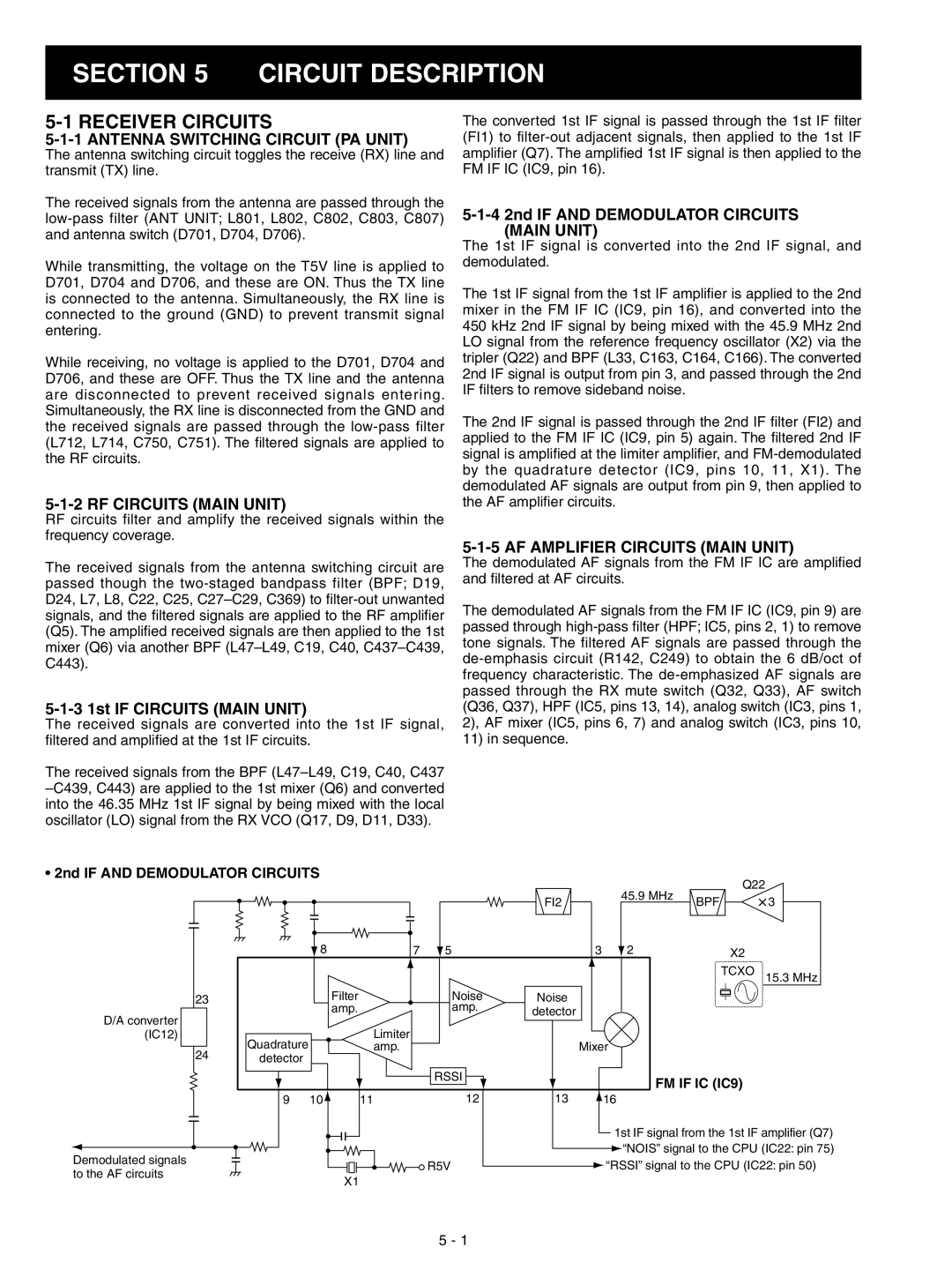
5-1-4 2nd IF AND DEMODULATOR CIRCUITS (MAIN UNIT)

The 1st IF signal is converted into the 2nd IF signal, and demodulated.

The 1st IF signal from the 1st IF amplifi er is applied to the 2nd mixer in the FM IF IC (IC9, pin 16), and converted into the 450 kHz 2nd IF signal by being mixed with the 45.9 MHz 2nd LO signal from the reference frequency oscillator (X2) via the tripler (Q22) and BPF (L33, C163, C164, C166). The converted 2nd IF signal is output from pin 3, and passed through the 2nd IF fi lters to remove sideband noise.

The 2nd IF signal is passed through the 2nd IF fi lter (FI2) and applied to the FM IF IC (IC9, pin 5) again. The fi ltered 2nd IF signal is amplifi ed at the limiter amplifi er, and FM-demodulated by the quadrature detector (IC9, pins 10, 11, X1). The demodulated AF signals are output from pin 9, then applied to the AF amplifi er circuits.

5-1-5 AF AMPLIFIER CIRCUITS (MAIN UNIT)

The demodulated AF signals from the FM IF IC are amplifi ed and fi ltered at AF circuits.

The demodulated AF signals from the FM IF IC (IC9, pin 9) are passed through high-pass fi lter (HPF; IC5, pins 2, 1) to remove tone signals. The filtered AF signals are passed through the de-emphasis circuit (R142, C249) to obtain the 6 dB/oct of frequency characteristic. The de-emphasized AF signals are passed through the RX mute switch (Q32, Q33), AF switch (Q36, Q37), HPF (IC5, pins 13, 14), analog switch (IC3, pins 1, 2), AF mixer (IC5, pins 6, 7) and analog switch (IC3, pins 10, 11) in sequence.

• 2nd IF AND DEMODULATOR CIRCUITS


Q22


45.9 MHz


FI2

BPF

3


8


7

5

3

2


X2


TCXO

15.3 MHz

23


Filter


Noise

Noise


D/A converter


amp.


amp.

detector


Limiter


(IC12)

Quadrature


24


amp.


Mixer


detector


RSSI


FM IF IC (IC9)


9

10

11


12

13

16


1st IF signal from the 1st IF amplifier (Q7)

Demodulated signals


“NOIS” signal to the CPU (IC22: pin 75)

R5V

“RSSI” signal to the CPU (IC22: pin 50)

to the AF circuits

X1


5 - 1

Page 8
Image 8
Icom IC-F3022S, IC-F3023S Circuit Description, Receiver Circuits, Antenna Switching Circuit PA Unit, RF Circuits Main Unit

IC-F3022T, IC-F3023T, IC-F3021S, IC-F3021T, IC-F3022S specifications

The Icom IC-F3023S, IC-F3022S, IC-F3021T, IC-F3021S, and IC-F3023T are part of Icom's robust lineup of mobile radios designed for reliable communication in diverse environments. These radios are renowned for their durability, advanced features, and user-friendly operation, making them ideal for organizations in public safety, security, and industrial sectors.

One of the standout features of these models is their compact and lightweight design. These radios are engineered for easy handling and mobility, ensuring that users can carry them throughout their workday without hassle. They are designed with ruggedness in mind, meeting military specifications for durability. This makes them resistant to water and dust, allowing for reliable performance even in harsh weather conditions.

The IC-F3023S and IC-F3022S models are equipped with powerful audio output, ensuring clear sound quality, even in noisy environments. These radios incorporate advanced digital signal processing (DSP) technology, which significantly enhances voice clarity and reduces background noise, making communication crisp and efficient.

For battery efficiency, these models feature a high-capacity lithium-ion battery, which provides long-lasting power for extended operation. With features like battery saver technology, users can maximize the lifespan of their batteries, reducing downtime and operational costs.

One of the key characteristics across these models is their versatility in communication. They support multiple frequency bands and have programmable channels, allowing users to customize their communication preferences according to their operational needs. The IC-F3021T and IC-F3021S variants also support Trunked Operation which facilitates seamless communication across larger teams.

Moreover, these radios support emergency features such as an emergency button that can be programmed for instant alerts, providing an additional layer of safety for users working in high-risk environments. The inclusion of various scanning features facilitates efficient channel monitoring, ensuring that users never miss critical communications.

In summary, the Icom IC-F3023S, IC-F3022S, IC-F3021T, IC-F3021S, and IC-F3023T radios are designed to meet the demands of professional users who require high-performance communication devices. With their rugged build, exceptional audio quality, and advanced features, these radios are invaluable tools in maintaining effective communication in any operational setting. Whether for construction sites, emergency services, or security details, these models offer the reliability and function that professionals need every day.