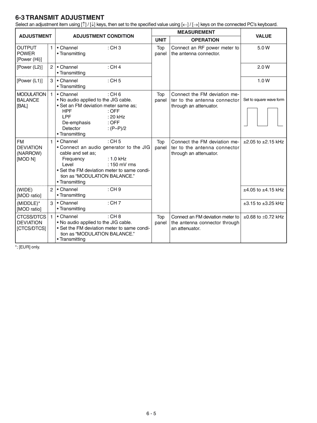
6-3 TRANSMIT ADJUSTMENT

Select an adjustment item using [] / [] keys, then set to the specified value using [] / [] keys on the connected PC’s keyboard.

ADJUSTMENT

ADJUSTMENT CONDITION


MEASUREMENT


VALUE


UNIT

OPERATION


OUTPUT

1

• Channel

: CH 3


Top

Connect an RF power meter to


5.0 W

POWER


• Transmitting


panel

the antenna connector.


[Power (Hi)]


[Power (L2)]

2

• Channel

: CH 4


2.0 W


• Transmitting


[Power (L1)]

3

• Channel

: CH 5


1.0 W


• Transmitting


MODULATION

1

• Channel

: CH 6


Top

Connect the FM deviation me-


BALANCE


• No audio applied to the JIG cable.


panel

ter to the antenna connector

Set to square wave form

[BAL]


• Set an FM deviation meter same as;


through an attenuator.


HPF

: OFF


LPF

: 20 kHz


De-emphasis

: OFF


Detector

: (P–P)/2


• Transmitting


FM

1

• Channel

: CH 5


Top

Connect the FM deviation me-

±2.05 to ±2.15 kHz

DEVIATION


• Connect an audio generator to the JIG


panel

ter to the antenna connector


(NARROW)


cable and set as;


through an attenuator.


[MOD N]


Frequency

: 1.0 kHz


Level

: 150 mV rms


Set the FM deviation meter to same condi- tion as “MODULATION BALANCE.”

Transmitting

(WIDE)

2

• Channel

: CH 9


±4.05 to ±4.15 kHz

[MOD ratio]


• Transmitting


(MIDDLE)*

3

• Channel

: CH 7


±3.15 to ±3.25 kHz

[MOD ratio]


• Transmitting


CTCSS/DTCS

1

• Channel

: CH 8

Top

Connect an FM deviation meter to ±0.68 to ±0.72 kHz

DEVIATION


• No audio applied to the JIG cable.

panel

the antenna connector through

[CTCS/DTCS]


• Set the FM deviation meter to same condi-


an attenuator.


tion as “MODULATION BALANCE.”


• Transmitting


*; [EUR] only.


6 - 5

Page 18
Image 18
Icom IC-F3023S, IC-F3022T, IC-F3022S, IC-F3021S, IC-F3021T, IC-F3023T service manual Transmit Adjustment

IC-F3022T, IC-F3023T, IC-F3021S, IC-F3021T, IC-F3022S specifications

The Icom IC-F3023S, IC-F3022S, IC-F3021T, IC-F3021S, and IC-F3023T are part of Icom's robust lineup of mobile radios designed for reliable communication in diverse environments. These radios are renowned for their durability, advanced features, and user-friendly operation, making them ideal for organizations in public safety, security, and industrial sectors.

One of the standout features of these models is their compact and lightweight design. These radios are engineered for easy handling and mobility, ensuring that users can carry them throughout their workday without hassle. They are designed with ruggedness in mind, meeting military specifications for durability. This makes them resistant to water and dust, allowing for reliable performance even in harsh weather conditions.

The IC-F3023S and IC-F3022S models are equipped with powerful audio output, ensuring clear sound quality, even in noisy environments. These radios incorporate advanced digital signal processing (DSP) technology, which significantly enhances voice clarity and reduces background noise, making communication crisp and efficient.

For battery efficiency, these models feature a high-capacity lithium-ion battery, which provides long-lasting power for extended operation. With features like battery saver technology, users can maximize the lifespan of their batteries, reducing downtime and operational costs.

One of the key characteristics across these models is their versatility in communication. They support multiple frequency bands and have programmable channels, allowing users to customize their communication preferences according to their operational needs. The IC-F3021T and IC-F3021S variants also support Trunked Operation which facilitates seamless communication across larger teams.

Moreover, these radios support emergency features such as an emergency button that can be programmed for instant alerts, providing an additional layer of safety for users working in high-risk environments. The inclusion of various scanning features facilitates efficient channel monitoring, ensuring that users never miss critical communications.

In summary, the Icom IC-F3023S, IC-F3022S, IC-F3021T, IC-F3021S, and IC-F3023T radios are designed to meet the demands of professional users who require high-performance communication devices. With their rugged build, exceptional audio quality, and advanced features, these radios are invaluable tools in maintaining effective communication in any operational setting. Whether for construction sites, emergency services, or security details, these models offer the reliability and function that professionals need every day.