4 OPTIONAL UNIT INSTALLATION
■Optional unit installation
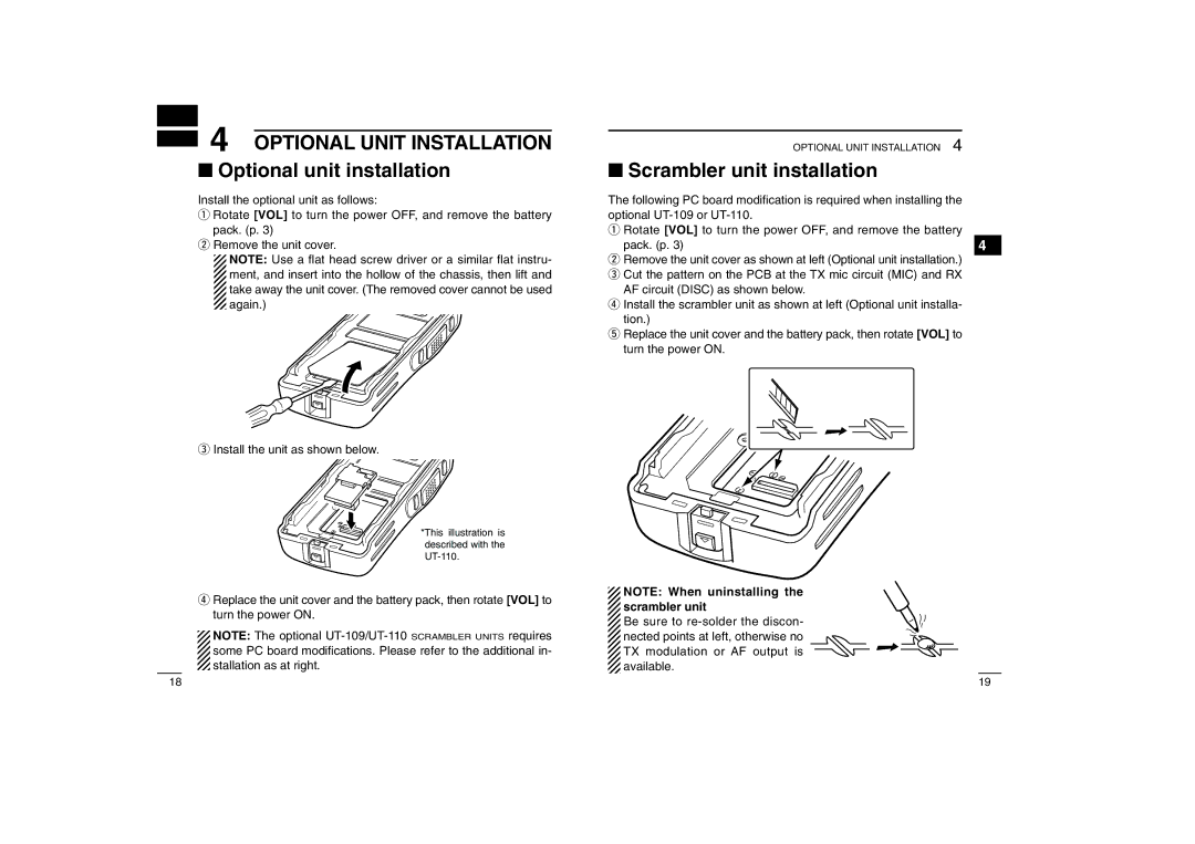
Install the optional unit as follows:
qRotate [VOL] to turn the power OFF, and remove the battery pack. (p. 3)
wRemove the unit cover.
NOTE: Use a flat head screw driver or a similar flat instru- ment, and insert into the hollow of the chassis, then lift and take away the unit cover. (The removed cover cannot be used again.)
eInstall the unit as shown below.
*This illustration is described with the
rReplace the unit cover and the battery pack, then rotate [VOL] to turn the power ON.
NOTE: The optional
OPTIONAL UNIT INSTALLATION 4
■Scrambler unit installation
The following PC board modification is required when installing the optional
qRotate [VOL] to turn the power OFF, and remove the battery
pack. (p. 3) | 4 |
wRemove the unit cover as shown at left (Optional unit installation.) e Cut the pattern on the PCB at the TX mic circuit (MIC) and RX
AF circuit (DISC) as shown below.
r Install the scrambler unit as shown at left (Optional unit installa- tion.)
t Replace the unit cover and the battery pack, then rotate [VOL] to turn the power ON.
NOTE: When uninstalling the scrambler unit
Be sure to
18 | 19 |