2 PANEL DESCRIPTION
■Front, top and side panels
q |
i![]()
![]()
![]() w
w
e
u
Speaker
y![]()
![]() r
r
t![]()
![]() Microphone
Microphone
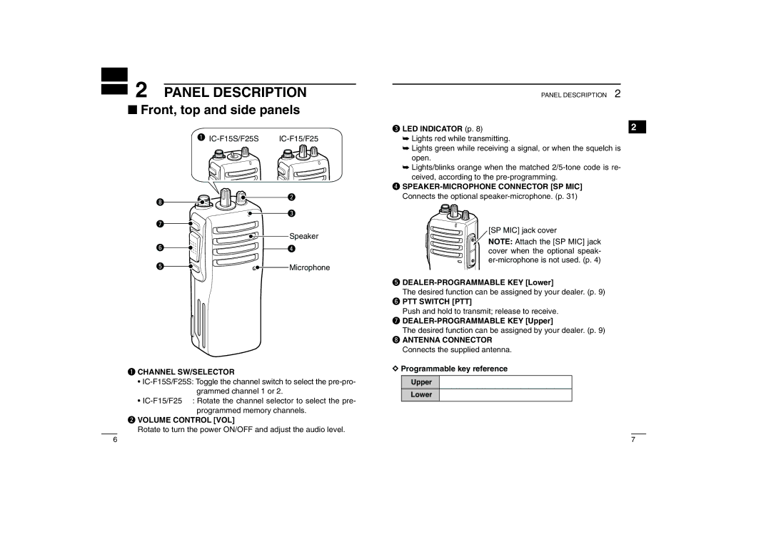
q CHANNEL SW/SELECTOR
•
•
w VOLUME CONTROL [VOL]
Rotate to turn the power ON/OFF and adjust the audio level.
PANEL DESCRIPTION | 2 |
e LED INDICATOR (p. 8) | 2 |
➥Lights red while transmitting.
➥Lights green while receiving a signal, or when the squelch is open.
➥Lights/blinks orange when the matched
r
Connects the optional
[SP MIC] jack cover
NOTE: Attach the [SP MIC] jack cover when the optional speak-
t DEALER-PROGRAMMABLE KEY [Lower]
The desired function can be assigned by your dealer. (p. 9) y PTT SWITCH [PTT]
Push and hold to transmit; release to receive. u
The desired function can be assigned by your dealer. (p. 9) i ANTENNA CONNECTOR
Connects the supplied antenna.
DProgrammable key reference
Upper Lower
6 | 7 |