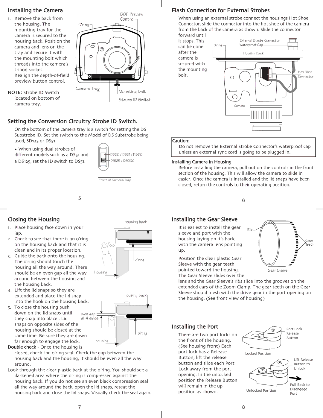
Installing the Camera 1. Remove the back from
the housing. The mounting tray for the camera is secured to the housing back. Position the camera and lens on the tray and secure it with the mounting bolt which threads into the camera’s tripod socket.
Realign the
NOTE: Strobe ID Switch located on bottom of camera tray.
O‘ring
Camera Tray
DOF Preview
Control
Mounting Bolt
Strobe ID Switch
Flash Connection for External Strobes | ||||||||||||||||||||||
When using an external strobe connect the housings Hot Shoe | ||||||||||||||||||||||
Connector, slide the connector into the hot shoe of the camera | ||||||||||||||||||||||
from the back of the camera as shown. Slide the connector | ||||||||||||||||||||||
forward until |
|
|
|
|
|
|
|
|
|
|
|
|
|
|
|
|
|
|
|
|
|
|
it stops. This |
|
|
|
|
|
|
| External Strobe Connector |
|
|
|
|
| |||||||||
|
|
|
|
|
|
|
|
|
|
|
|
|
| |||||||||
|
|
|
|
|
|
|
|
|
|
|
|
|
| |||||||||
can be done | O'ring |
|
|
|
|
| Waterproof Cap |
|
|
|
|
|
|
|
| |||||||
after the |
|
|
|
|
|
|
|
|
|
|
|
|
|
|
|
|
|
|
|
|
|
|
|
|
|
|
|
|
| Housing Back |
| ||||||||||||||
camera is |
|
|
|
|
|
|
|
|
|
|
|
|
|
|
|
|
|
|
|
|
|
|
|
|
|
|
|
|
|
|
|
|
|
|
|
|
|
|
|
|
|
|
|
| |
secured with |
|
|
|
|
|
|
|
|
|
|
|
|
|
|
|
|
|
|
|
|
|
|
|
|
|
|
|
|
|
|
|
|
|
|
|
|
|
|
|
|
|
|
|
| |
the mounting |
|
|
|
|
|
|
|
|
|
|
|
|
|
|
|
|
|
|
| Hot Shoe | ||
|
|
|
|
|
|
|
|
|
|
|
|
|
|
|
|
|
|
| ||||
bolt. |
|
|
|
|
|
|
|
|
|
|
|
|
|
|
|
|
|
|
|
| Connector | |
|
|
|
|
|
|
|
|
|
|
|
|
|
|
|
|
|
|
|
| |||
|
|
|
|
|
|
|
|
|
|
|
|
|
|
|
|
|
|
|
|
|
|
|
Camera
Setting the Conversion Circuitry Strobe ID Switch. | |||||||||||||||||||
| On the bottom of the camera tray is a switch for setting the DS | ||||||||||||||||||
| Substrobe ID. Set the switch to the Model of DS Substrobe being | ||||||||||||||||||
| used, SD125 or DS51. |
|
|
|
|
|
|
|
|
|
|
|
|
|
|
|
|
|
|
| • When using dual strobes of |
|
|
|
|
|
|
|
|
|
|
|
|
|
|
|
|
|
|
| different models such as a DS51 and |
|
|
|
|
|
|
|
| DS50 / DS51 / DS80 | |||||||||
|
|
|
|
|
|
|
|
| |||||||||||
| a DS125, set the ID switch to DS51. |
|
|
|
|
|
|
|
| DS125 / DS200 | |||||||||
|
|
|
|
|
|
|
|
| |||||||||||
|
|
|
|
|
|
|
|
|
|
|
|
|
|
|
|
|
| ||
|
|
|
|
|
|
|
|
| |||||||||||
|
|
|
|
| Front of Camera/Tray | ||||||||||||||
|
| 5 |
|
|
|
|
|
|
|
|
|
|
|
|
|
|
|
|
|
Closing the Housing |
|
|
|
|
|
|
|
|
|
|
| housing back |
| ||||||
1. | Place housing face down in your |
|
|
|
|
|
|
|
|
|
|
|
|
|
|
|
|
| |
| lap. |
|
|
|
|
|
|
|
|
|
|
|
|
|
|
|
|
|
|
|
|
|
|
|
|
|
|
|
|
|
|
|
|
|
|
|
|
| |
2. | Check to see that there is an o’ring |
|
|
|
|
|
|
|
|
|
|
|
|
|
|
|
|
| |
| on the housing back and that it is |
|
|
|
|
|
|
|
|
|
|
|
|
|
|
|
|
| |
3. | clean and in its proper location. |
|
|
|
|
|
|
|
|
|
|
|
|
|
|
|
|
| |
|
|
|
|
|
|
|
|
|
|
|
|
|
|
|
|
| |||
Guide the back onto the housing. |
|
|
|
|
|
|
|
|
|
|
|
|
|
|
|
|
| ||
| The o’ring should touch the |
|
|
|
|
|
|
|
|
|
|
|
|
|
|
| o’ring | ||
|
|
|
|
|
|
|
|
|
|
|
|
|
|
|
| ||||
| housing all the way around. There |
|
|
|
|
|
|
|
|
|
|
|
|
|
|
|
|
| |
| should be an even gap all the way | housing | |||||||||||||||||
| around between the housing and |
|
|
|
|
|
|
|
|
|
|
|
|
|
|
|
|
| |
4. | the housing back. |
|
|
|
|
|
|
|
|
|
|
|
|
|
|
|
|
|
|
Lift the lid snaps so they are |
|
|
|
|
|
|
|
|
|
|
|
|
|
|
|
|
|
| |
| extended and place the lid snap |
|
|
|
|
|
|
|
|
|
| housing back |
|
| |||||
|
|
|
|
|
|
|
|
|
|
|
| ||||||||
| into the hook on the housing back. |
|
|
|
|
|
|
|
|
|
|
|
|
|
|
|
|
| |
|
|
|
|
|
|
|
|
|
|
|
|
|
|
|
|
|
| ||
5. | To close the housing push |
|
|
|
|
|
|
|
|
|
|
|
|
|
|
|
|
|
|
|
|
|
|
|
|
|
|
|
|
|
|
|
|
|
|
|
| ||
| down on the lid snaps until | even gap |
|
|
|
|
|
|
|
|
|
|
|
|
|
| |||
|
|
|
|
|
|
| |||||||||||||
|
|
|
|
|
|
|
|
|
|
|
|
|
|
| |||||
|
|
|
|
|
| ||||||||||||||
| they snap into place . Lid |
|
|
|
|
|
|
|
|
|
|
|
|
|
|
|
|
|
|
Caution:
Do not remove the External Strobe Connector’s waterproof cap unless an external sync cord is going to be plugged in.
Installing Camera in Housing
Before installing the camera, pull out on the controls in the front section of the housing. This will allow the camera to slide in easier. Once the camera is installed and the lid snaps have been closed, return the controls to their operating position.
6 |
|
|
|
|
|
|
|
|
|
Installing the Gear Sleeve |
|
|
|
|
|
|
|
|
|
It is easiest to install the gear |
|
|
|
|
|
|
|
|
|
Rib | |||||||||
sleeve and port with the |
|
|
|
|
|
|
|
|
|
housing laying on it’s back |
|
|
|
|
|
|
|
| Gear |
with the camera lens pointing |
|
|
|
|
|
|
|
| Teeth |
|
|
|
|
|
|
|
| ||
|
|
|
|
|
|
|
| ||
|
|
|
|
|
|
|
| ||
up. |
|
|
|
|
|
|
|
|
|
|
|
|
|
|
|
|
|
| |
|
|
|
|
|
|
|
|
| |
|
|
|
|
|
|
|
|
| |
Position the clear plastic Gear |
|
|
|
|
|
|
|
|
|
|
|
|
|
|
|
|
|
| |
|
|
|
|
|
|
|
|
| |
|
|
|
|
|
|
|
|
| |
|
|
|
|
|
|
|
|
| |
|
|
|
|
|
|
|
|
| |
|
|
|
|
|
|
|
|
| |
Sleeve with the gear teeth |
|
|
|
|
|
|
|
|
|
|
|
|
|
|
|
|
|
| |
|
|
|
|
|
|
|
|
| |
|
|
|
|
|
|
|
|
| |
pointed toward the housing. |
|
|
|
|
|
|
|
| |
Gear Sleeve |
|
|
|
|
|
| |||
|
|
|
|
|
| ||||
|
|
|
|
|
| ||||
The Gear Sleeve slides over the |
|
|
|
|
|
|
|
|
|
lens and the Gear Sleeve’s ribs slide into the grooves on the extended ears of the Zoom Clamp. The gear teeth on the Gear Sleeve should mesh with the drive gear in the port opening on the housing. (See front view of housing)
snaps on opposite sides of the all 4 sides |
|
| |||
|
| ||||
|
| ||||
housing should be closed at the |
|
|
|
| o’ring |
same time. Be sure they are down |
|
|
|
|
|
|
|
|
|
| |
far enough to engage the lock. | housing | ||||
Double check - Once the housing is |
|
|
|
|
|
closed, check the o’ring seal. Check the gap between the | |||||
housing back and the housing, it should be even all the way | |||||
around. |
|
|
|
|
|
Look through the clear plastic back at the o’ring. You should see a darkened area where the o’ring is compressed against the housing back. If you do not see an even black compression seal all the way around the back, open the lid snaps, reseat the housing back and close the lid snaps. Visually check the seal again.
Installing the Port There are two port locks on the front of the housing. (See housing front) Each port lock has a Release Button, lift the release button and slide each Port Lock away from the port opening. In the unlocked position the Release Button will remain in the up position as shown.
Port Lock
Release
Button
Locked Position
Lift Release Button to Unlock
Pull Back to
Unlocked Position Disengage Port
7 | 8 |