nIn Force-100 mode, the McBasic 10/100 configures specifically as a 100BASE-TX/100BASE-SX or FX media converter. Note that Force-100 implies the rejection of 10 Mbps signals.
To enable Force-100 mode, set Dip switch 6 to the ON position (Dip switch 4 must be in the OFF position). To disable Force-100 mode, move Dip switch 6 to OFF (factory default).
Note: Force mode should be used when any of the devices connected to the media converters DO NOT support Auto-Negotiation. Do NOT enable both Dip switches 5 and 6. Only one switch should be enabled at any given time.
IMPORTANT: It necessary to power down and then power up again before the above Dip switch changes will take effect!
Connecting Half Duplex or Full Duplex and 10 or 100 Mbps Devices
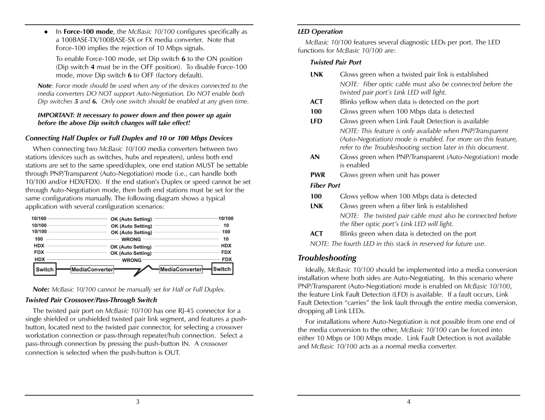
When connecting two McBasic 10/100 media converters between two stations (devices such as switches, hubs and repeaters), unless both end stations are set to the same speed/duplex, one end station MUST be settable through PNP/Transparent (Auto-Negotiation) mode (i.e., can handle both 10/100 and/or HDX/FDX). If the end station’s Duplex or speed cannot be set through Auto-Negotiation mode, then both end stations must be set for the same configurations manually. The following diagram shows a typical application with several configuration scenarios:
Note: McBasic 10/100 cannot be manually set for Half or Full Duplex.
Twisted Pair Crossover/Pass-Through Switch
The twisted pair port on McBasic 10/100 has one RJ-45 connector for a single shielded or unshielded twisted pair link segment, and features a push- button, located next to the twisted pair connector, for selecting a crossover workstation connection or pass-through repeater/hub connection. Select a pass-through connection by pressing the push-button IN. A crossover connection is selected when the push-button is OUT.
LED Operation
McBasic 10/100 features several diagnostic LEDs per port. The LED functions for McBasic 10/100 are:
Twisted Pair Port
LNK Glows green when a twisted pair link is established
NOTE: Fiber optic cable must also be connected before the twisted pair port’s Link LED will light.
ACT Blinks yellow when data is detected on the port
100Glows green when 100 Mbps data is detected
LFD Glows green when Link Fault Detection is available
NOTE: This feature is only available when PNP/Transparent (Auto-Negotiation) mode is enabled. For more on this feature, refer to the Troubleshooting section later in this document.
AN Glows green when PNP/Transparent (Auto-Negotiation) mode is enabled
PWR Glows green when unit has power
Fiber Port
100Glows yellow when 100 Mbps data is detected
LNK Glows green when a fiber link is established
NOTE: The twisted pair cable must also be connected before the fiber optic port’s Link LED will light.
ACT Blinks green when data is detected on the port
NOTE: The fourth LED in this stack in reserved for future use.
Troubleshooting
Ideally, McBasic 10/100 should be implemented into a media conversion installation where both sides are Auto-Negotiating. In this scenario where PNP/Transparent (Auto-Negotiation) mode is enabled on McBasic 10/100, the feature Link Fault Detection (LFD) is available. If a fault occurs, Link Fault Detection “carries” the link fault through the entire media conversion, dropping all Link LEDs.
For installations where Auto-Negotiation is not possible from one end of the media conversion to the other, McBasic 10/100 can be forced into either 10 Mbps or 100 Mbps mode. Link Fault Detection is not available and McBasic 10/100 acts as a normal media converter.