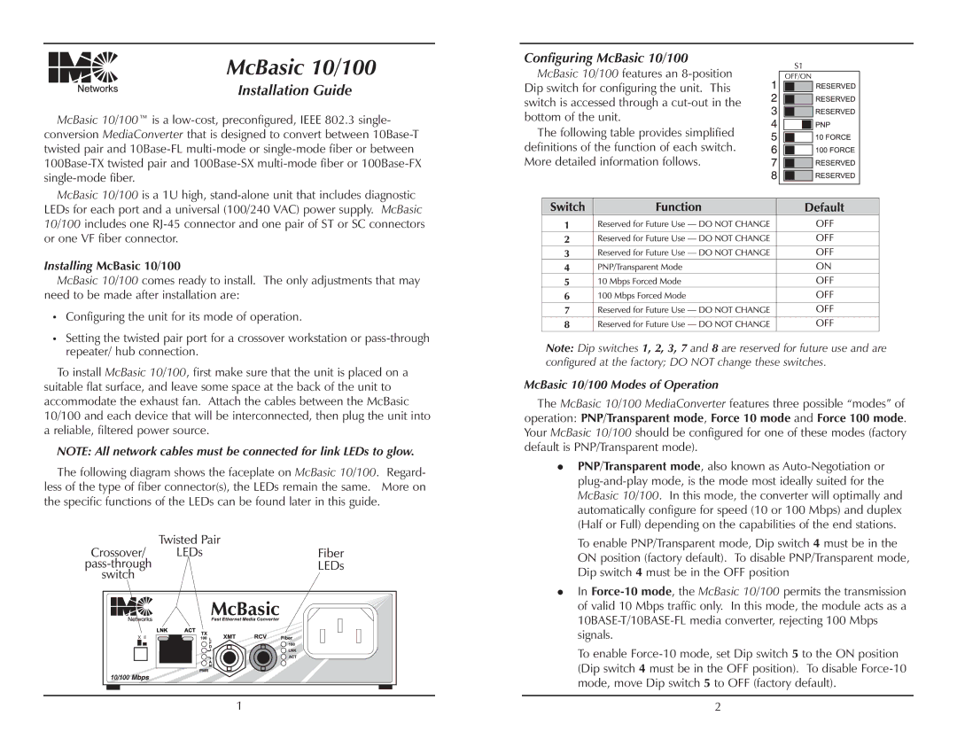
McBasic 10/100
Installation Guide
McBasic 10/100™ is a
McBasic 10/100 is a 1U high,
Installing McBasic 10/100
McBasic 10/100 comes ready to install. The only adjustments that may need to be made after installation are:
lConfiguring the unit for its mode of operation.
lSetting the twisted pair port for a crossover workstation or
To install McBasic 10/100, first make sure that the unit is placed on a suitable flat surface, and leave some space at the back of the unit to accommodate the exhaust fan. Attach the cables between the McBasic 10/100 and each device that will be interconnected, then plug the unit into a reliable, filtered power source.
NOTE: All network cables must be connected for link LEDs to glow.
The following diagram shows the faceplate on McBasic 10/100. Regard- less of the type of fiber connector(s), the LEDs remain the same. More on the specific functions of the LEDs can be found later in this guide.
1 |
Configuring McBasic 10/100
McBasic 10/100 features an
The following table provides simplified definitions of the function of each switch. More detailed information follows.
Note: Dip switches 1, 2, 3, 7 and 8 are reserved for future use and are configured at the factory; DO NOT change these switches.
McBasic 10/100 Modes of Operation
The McBasic 10/100 MediaConverter features three possible “modes” of operation: PNP/Transparent mode, Force 10 mode and Force 100 mode. Your McBasic 10/100 should be configured for one of these modes (factory default is PNP/Transparent mode).
nPNP/Transparent mode, also known as
To enable PNP/Transparent mode, Dip switch 4 must be in the ON position (factory default). To disable PNP/Transparent mode, Dip switch 4 must be in the OFF position
nIn
To enable
2
