ASSEMBLY INSTRUCTION
Tools Required Assembling the Machine: Two Adjustable Wrenches and Allen
Wrenches. NOTE: It is strongly recommended two or more people assembling this machine to avoid possible injury.
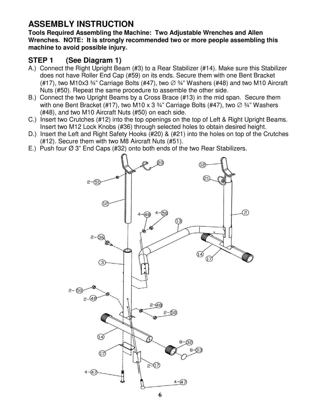
STEP 1 | (See Diagram 1) |
A.) Connect the Right Upright Beam (#3) to a Rear Stabilizer (#14). Make sure this Stabilizer | |
does not have Roller End Cap (#59) on its ends. Secure them with one Bent Bracket | |
(#17), two M10x3 ¾” Carriage Bolts (#47), two ∅ ¾” Washers (#48) and two M10 Aircraft | |
Nuts (#50). Repeat the same procedure to assemble the other side.
B.) Connect the two Upright Beams by a Cross Brace (#13) in the mid span. | Secure them | |
| with one Bent Bracket (#17), two M10 x 3 ¾” Carriage Bolts (#47), two ∅ | ¾” Washers |
| (#48), and two M10 Aircraft Nuts (#50) on each side. |
|
C.) | Insert two Crutches (#12) into the top openings on the top of Left & Right Upright Beams. | |
| Insert two M12 Lock Knobs (#36) through selected holes to obtain desired height. | |
D.) | Insert the Left and Right Safety Hooks (#20) & (#21) into the holes on top of the Crutches | |
| (#12). Secure them with two M8 Aircraft Nuts (#51). |
|
E.) | Push four Ø 3” End Caps (#32) onto both ends of the two Rear Stabilizers. | |
6