STEP 2 (See Diagram 2)
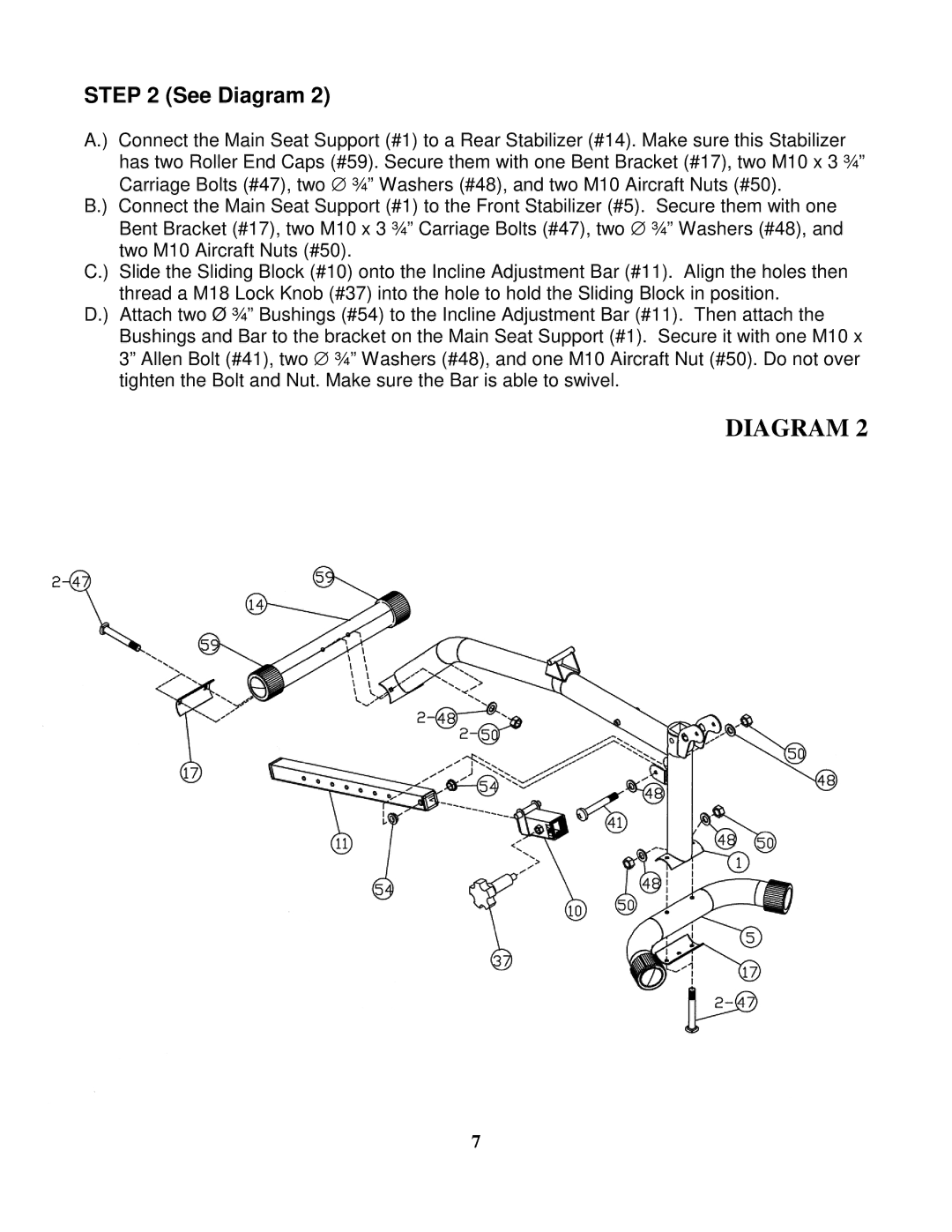
A.) Connect the Main Seat Support (#1) to a Rear Stabilizer (#14). Make sure this Stabilizer has two Roller End Caps (#59). Secure them with one Bent Bracket (#17), two M10 x 3 ¾” Carriage Bolts (#47), two ∅ ¾” Washers (#48), and two M10 Aircraft Nuts (#50).
B.) Connect the Main Seat Support (#1) to the Front Stabilizer (#5). Secure them with one Bent Bracket (#17), two M10 x 3 ¾” Carriage Bolts (#47), two ∅ ¾” Washers (#48), and two M10 Aircraft Nuts (#50).
C.) Slide the Sliding Block (#10) onto the Incline Adjustment Bar (#11). Align the holes then thread a M18 Lock Knob (#37) into the hole to hold the Sliding Block in position.
D.) Attach two Ø ¾” Bushings (#54) to the Incline Adjustment Bar (#11). Then attach the Bushings and Bar to the bracket on the Main Seat Support (#1). Secure it with one M10 x 3” Allen Bolt (#41), two ∅ ¾” Washers (#48), and one M10 Aircraft Nut (#50). Do not over tighten the Bolt and Nut. Make sure the Bar is able to swivel.
DIAGRAM 2
7