STEP 5 (See Diagram 5)
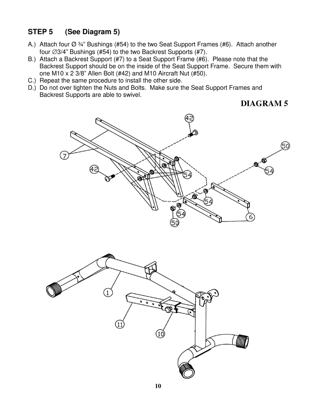
A.) Attach four Ø ¾” Bushings (#54) to the two Seat Support Frames (#6). Attach another four ∅ 3/4” Bushings (#54) to the two Backrest Supports (#7).
B.) Attach a Backrest Support (#7) to a Seat Support Frame (#6). Please note that the Backrest Support should be on the inside of the Seat Support Frame. Secure them with one M10 x 2 3/8” Allen Bolt (#42) and M10 Aircraft Nut (#50).
C.) Repeat the same procedure to install the other side.
D.) Do not over tighten the Nuts and Bolts. Make sure the Seat Support Frames and Backrest Supports are able to swivel.
DIAGRAM 5
10