STEP 2 (See Diagram 2)
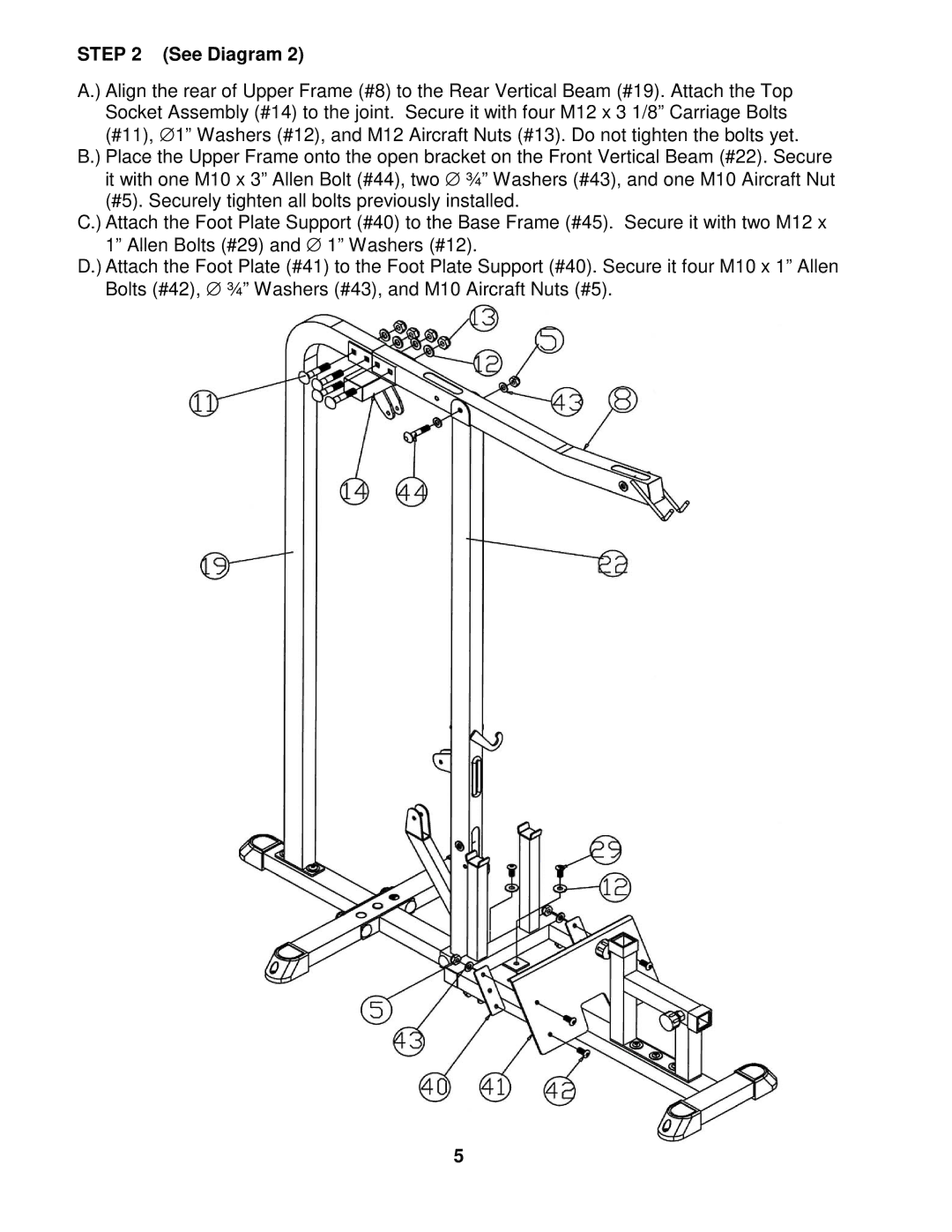
A.) Align the rear of Upper Frame (#8) to the Rear Vertical Beam (#19). Attach the Top Socket Assembly (#14) to the joint. Secure it with four M12 x 3 1/8” Carriage Bolts (#11), ∅ 1” Washers (#12), and M12 Aircraft Nuts (#13). Do not tighten the bolts yet.
B.) Place the Upper Frame onto the open bracket on the Front Vertical Beam (#22). Secure it with one M10 x 3” Allen Bolt (#44), two ∅ ¾” Washers (#43), and one M10 Aircraft Nut (#5). Securely tighten all bolts previously installed.
C.) Attach the Foot Plate Support (#40) to the Base Frame (#45). Secure it with two M12 x 1” Allen Bolts (#29) and ∅ 1” Washers (#12).
D.) Attach the Foot Plate (#41) to the Foot Plate Support (#40). Secure it four M10 x 1” Allen Bolts (#42), ∅ ¾” Washers (#43), and M10 Aircraft Nuts (#5).
5