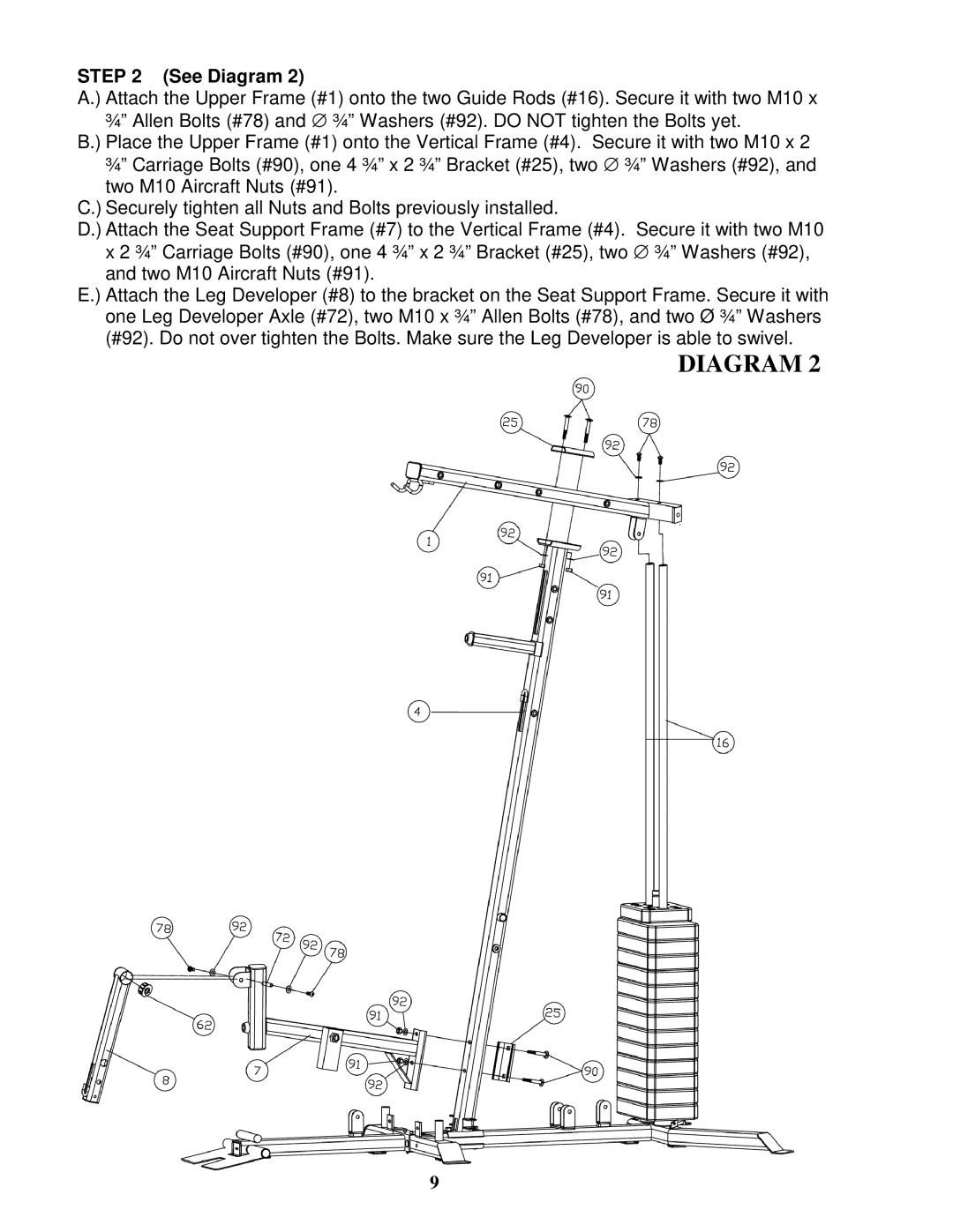
STEP 2 (See Diagram 2)
A.) Attach the Upper Frame (#1) onto the two Guide Rods (#16). Secure it with two M10 x ¾” Allen Bolts (#78) and ∅ ¾” Washers (#92). DO NOT tighten the Bolts yet.
B.) Place the Upper Frame (#1) onto the Vertical Frame (#4). Secure it with two M10 x 2 ¾” Carriage Bolts (#90), one 4 ¾” x 2 ¾” Bracket (#25), two ∅ ¾” Washers (#92), and two M10 Aircraft Nuts (#91).
C.) Securely tighten all Nuts and Bolts previously installed.
D.) Attach the Seat Support Frame (#7) to the Vertical Frame (#4). Secure it with two M10 x 2 ¾” Carriage Bolts (#90), one 4 ¾” x 2 ¾” Bracket (#25), two ∅ ¾” Washers (#92), and two M10 Aircraft Nuts (#91).
E.) Attach the Leg Developer (#8) to the bracket on the Seat Support Frame. Secure it with one Leg Developer Axle (#72), two M10 x ¾” Allen Bolts (#78), and two Ø ¾” Washers (#92). Do not over tighten the Bolts. Make sure the Leg Developer is able to swivel.
DIAGRAM 2
9