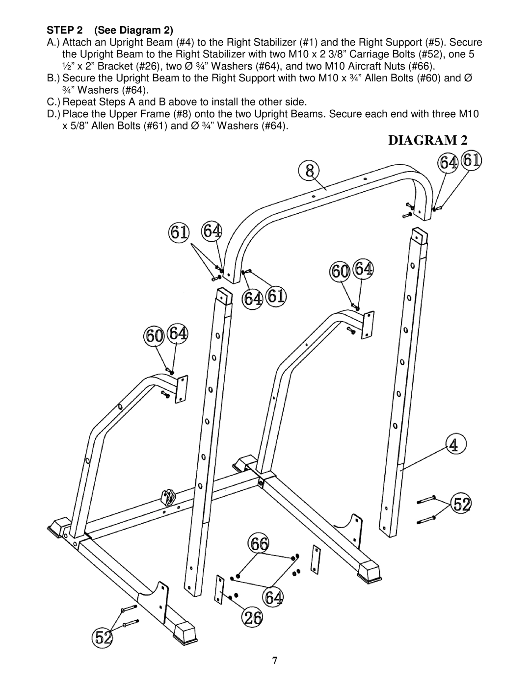
STEP 2 (See Diagram 2)
A.) Attach an Upright Beam (#4) to the Right Stabilizer (#1) and the Right Support (#5). Secure the Upright Beam to the Right Stabilizer with two M10 x 2 3/8” Carriage Bolts (#52), one 5 ½” x 2” Bracket (#26), two Ø ¾” Washers (#64), and two M10 Aircraft Nuts (#66).
B.) Secure the Upright Beam to the Right Support with two M10 x ¾” Allen Bolts (#60) and Ø ¾” Washers (#64).
C.) Repeat Steps A and B above to install the other side.
D.) Place the Upper Frame (#8) onto the two Upright Beams. Secure each end with three M10 x 5/8” Allen Bolts (#61) and Ø ¾” Washers (#64).
DIAGRAM 2
7