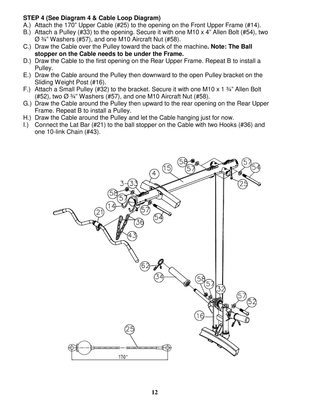
STEP 4 (See Diagram 4 & Cable Loop Diagram)
A.) Attach the 170” Upper Cable (#25) to the opening on the Front Upper Frame (#14). B.) Attach a Pulley (#33) to the opening. Secure it with one M10 x 4” Allen Bolt (#54), two
Ø ¾” Washers (#57), and one M10 Aircraft Nut (#58).
C.) Draw the Cable over the Pulley toward the back of the machine. Note: The Ball stopper on the Cable needs to be under the Frame.
D.) Draw the Cable to the first opening on the Rear Upper Frame. Repeat B to install a Pulley.
E.) Draw the Cable around the Pulley then downward to the open Pulley bracket on the Sliding Weight Post (#16).
F.) Attach a Small Pulley (#32) to the bracket. Secure it with one M10 x 1 ¾” Allen Bolt
(#52), two Ø ¾” Washers (#57), and one M10 Aircraft Nut (#58).
G.) Draw the Cable around the Pulley then upward to the rear opening on the Rear Upper
| Frame. Repeat B to install a Pulley. |
H.) | Draw the Cable around the Pulley and let the Cable hanging just for now. |
I.) | Connect the Lat Bar (#21) to the ball stopper on the Cable with two Hooks (#36) and |
| one |
12