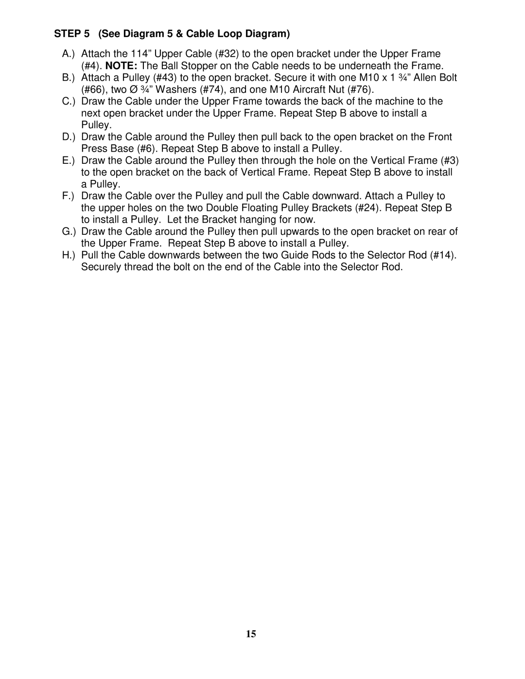
STEP 5 (See Diagram 5 & Cable Loop Diagram)
A.) Attach the 114” Upper Cable (#32) to the open bracket under the Upper Frame (#4). NOTE: The Ball Stopper on the Cable needs to be underneath the Frame.
B.) Attach a Pulley (#43) to the open bracket. Secure it with one M10 x 1 ¾” Allen Bolt (#66), two Ø ¾” Washers (#74), and one M10 Aircraft Nut (#76).
C.) Draw the Cable under the Upper Frame towards the back of the machine to the next open bracket under the Upper Frame. Repeat Step B above to install a Pulley.
D.) Draw the Cable around the Pulley then pull back to the open bracket on the Front Press Base (#6). Repeat Step B above to install a Pulley.
E.) Draw the Cable around the Pulley then through the hole on the Vertical Frame (#3) to the open bracket on the back of Vertical Frame. Repeat Step B above to install a Pulley.
F.) Draw the Cable over the Pulley and pull the Cable downward. Attach a Pulley to the upper holes on the two Double Floating Pulley Brackets (#24). Repeat Step B to install a Pulley. Let the Bracket hanging for now.
G.) Draw the Cable around the Pulley then pull upwards to the open bracket on rear of the Upper Frame. Repeat Step B above to install a Pulley.
H.) Pull the Cable downwards between the two Guide Rods to the Selector Rod (#14). Securely thread the bolt on the end of the Cable into the Selector Rod.
15