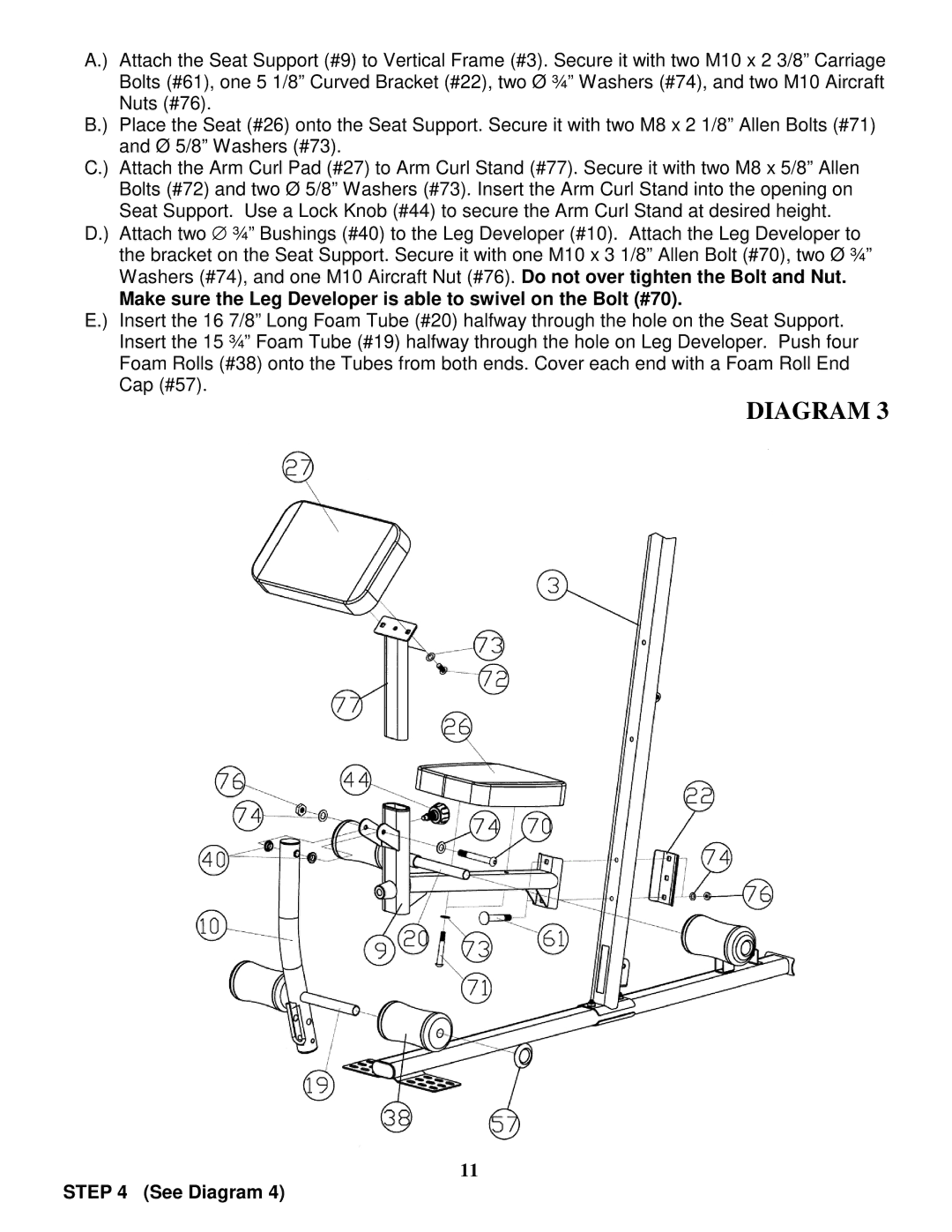
A.) Attach the Seat Support (#9) to Vertical Frame (#3). Secure it with two M10 x 2 3/8” Carriage Bolts (#61), one 5 1/8” Curved Bracket (#22), two Ø ¾” Washers (#74), and two M10 Aircraft Nuts (#76).
B.) Place the Seat (#26) onto the Seat Support. Secure it with two M8 x 2 1/8” Allen Bolts (#71) and Ø 5/8” Washers (#73).
C.) Attach the Arm Curl Pad (#27) to Arm Curl Stand (#77). Secure it with two M8 x 5/8” Allen Bolts (#72) and two Ø 5/8” Washers (#73). Insert the Arm Curl Stand into the opening on Seat Support. Use a Lock Knob (#44) to secure the Arm Curl Stand at desired height.
D.) Attach two ∅ ¾” Bushings (#40) to the Leg Developer (#10). Attach the Leg Developer to the bracket on the Seat Support. Secure it with one M10 x 3 1/8” Allen Bolt (#70), two Ø ¾” Washers (#74), and one M10 Aircraft Nut (#76). Do not over tighten the Bolt and Nut.
Make sure the Leg Developer is able to swivel on the Bolt (#70).
E.) Insert the 16 7/8” Long Foam Tube (#20) halfway through the hole on the Seat Support. Insert the 15 ¾” Foam Tube (#19) halfway through the hole on Leg Developer. Push four Foam Rolls (#38) onto the Tubes from both ends. Cover each end with a Foam Roll End Cap (#57).
DIAGRAM 3
11
STEP 4 (See Diagram 4)