PUMP OPTION DESCRIPTION CHART
650875- |
| X |
|
|
| X |
|
|
| X |
| PACKING MATERIAL (Packings are upper and lower unless noted) | |||||||||
|
|
|
|
|
|
|
| 3 - Glass filled PTFE | J - | Polyurethane (upper) | |||||||||||
|
|
|
|
|
| ||||||||||||||||
|
|
|
|
|
|
|
|
|
|
|
|
|
|
|
|
|
|
| C - |
|
|
Packing Material |
|
|
|
|
|
|
|
|
|
|
|
|
|
|
|
|
|
| F - | P - | |
|
|
|
|
|
|
|
|
|
|
|
|
|
|
|
|
| |||||
|
|
|
|
|
|
|
|
|
|
|
|
|
|
|
|
| |||||
Spring Arrangement |
|
|
|
|
|
|
|
|
|
|
| R - | Glass filled PTFE / | ||||||||
|
|
|
|
|
|
|
|
|
|
| |||||||||||
Plunger Type |
|
|
|
|
|
|
|
|
|
| Glass filled PTFE (lower) | ||||||||||
|
|
|
|
|
|
| |||||||||||||||
SPRING ARRANGEMENT | PLUNGER TYPE | |||
3 | - No spring | E - Carbon steel with hard chrome plating | ||
4 | - Multiple wave spring |
| ||
8 | - No spring with alternate solvent cup |
| ||
9 | - Multiple wave spring with alternate solvent cup | |||
|
|
|
| |
|
|
|
|
|
GENERAL DESCRIPTION |
|
| PUMP CONNECTION - UPPER / LOWER | |
The
The motor is connected to the lower pump end by a spacer section. This allows for lubrication of the upper packing gland and prevents motor contamination because of normal wear and eventual leak- age through the material packing gland. Be sure the solvent cup is adequately filled with lubricant to protect the upper packings and insure longest service life.
![]()
![]() WARNING HAZARDOUS PRESSURE. Do not exceed maxi- mum operating pressure of 2250 p.s.i. (155.2 bar) at 90 p.s.i. (6.2 bar) inlet air pressure.
WARNING HAZARDOUS PRESSURE. Do not exceed maxi- mum operating pressure of 2250 p.s.i. (155.2 bar) at 90 p.s.i. (6.2 bar) inlet air pressure.
Pump Ratio X | = | Maximum Pump |
Inlet Pressure to Pump Motor |
| Fluid Pressure |
Pump ratio is an expression of the relationship between the pump motor area and the lower pump end area. EXAMPLE: When 150 p.s.i. (10.3 bar) inlet pressure is supplied to the motor of a 4:1 ratio pump, it will develop a maximum of 600 p.s.i. (41.4 bar) fluid pressure (at no flow) - as the fluid control is opened, the flow rate will increase as the motor cycle rate increases to keep up with the demand.
![]()
![]() WARNING Refer to general information sheet for additional safety precautions and important information.
WARNING Refer to general information sheet for additional safety precautions and important information.
NOTICE: Thermal expansion can occur when the fluid in the mate-
rial lines is exposed to elevated temperatures. Example: Material lines located in a
Replacement warning label (pn 92325) is available upon re- quest.
TROUBLE SHOOTING
Pump problems can occur in either the air motor section or the lower pump end section. Use these basic guidelines to help deter- mine which section is affected.
Pump will not cycle.
yBe certain to first check for
yRefer to the motor manual for trouble shooting if the pump does not cycle and / or air leaks from the air motor.
yDamaged motor. Service the motor.
Pump cycles but does not deliver material.
yRefer to the lower pump end manual for further trouble shoot- ing.
NOTE: All threads are right hand.
1.Lay the pump assembly on a work bench.
2.Remove the three
3.Pull the air motor from the lower pump end until the motor piston rod is in the “down” position and the lower pump end rod is in the “up” position.
4.Remove the three spacer rods by removing the three
5.Using
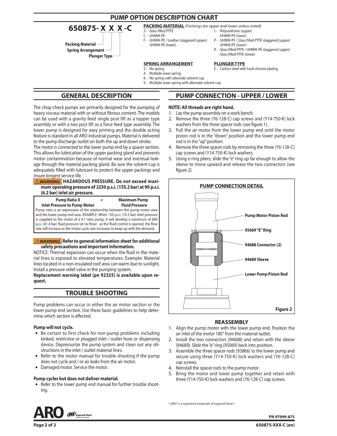
PUMP CONNECTION DETAIL
Pump Motor Piston Rod
95069 “E” Ring
94688 Connector (2)
94689 Sleeve
Lower Pump Piston Rod
Figure 2
REASSEMBLY
1.Align the pump motor with the lower pump end. Position the air inlet of the motor 180° from the material outlet.
2.Install the two connectors (94688) and retain with the sleeve (94689). Slide the “e” ring (95069) back into position.
3.Assemble the three spacer rods (93866) to the lower pump and secure using three
4.Reinstall the spacer rods to the pump motor.
5.Bring the motor and lower pump together and retain with three
y ARO® is a registered trademark of Ingersoll Rand y
PN
Page 2 of 2 |