STEP 4 (See Diagram 4)
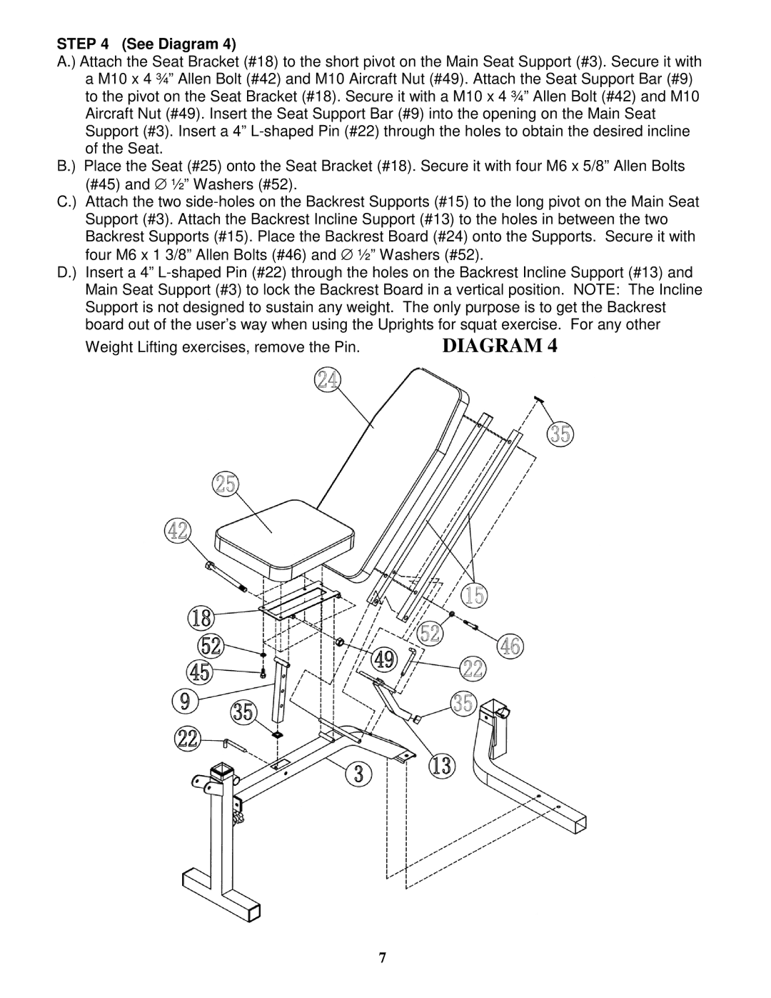
A.) Attach the Seat Bracket (#18) to the short pivot on the Main Seat Support (#3). Secure it with a M10 x 4 ¾” Allen Bolt (#42) and M10 Aircraft Nut (#49). Attach the Seat Support Bar (#9) to the pivot on the Seat Bracket (#18). Secure it with a M10 x 4 ¾” Allen Bolt (#42) and M10 Aircraft Nut (#49). Insert the Seat Support Bar (#9) into the opening on the Main Seat Support (#3). Insert a 4” L-shaped Pin (#22) through the holes to obtain the desired incline of the Seat.
B.) Place the Seat (#25) onto the Seat Bracket (#18). Secure it with four M6 x 5/8” Allen Bolts (#45) and ∅ ½” Washers (#52).
C.) Attach the two side-holes on the Backrest Supports (#15) to the long pivot on the Main Seat Support (#3). Attach the Backrest Incline Support (#13) to the holes in between the two Backrest Supports (#15). Place the Backrest Board (#24) onto the Supports. Secure it with four M6 x 1 3/8” Allen Bolts (#46) and ∅ ½” Washers (#52).
D.) Insert a 4” L-shaped Pin (#22) through the holes on the Backrest Incline Support (#13) and Main Seat Support (#3) to lock the Backrest Board in a vertical position. NOTE: The Incline Support is not designed to sustain any weight. The only purpose is to get the Backrest board out of the user’s way when using the Uprights for squat exercise. For any other
Weight Lifting exercises, remove the Pin. | DIAGRAM 4 |