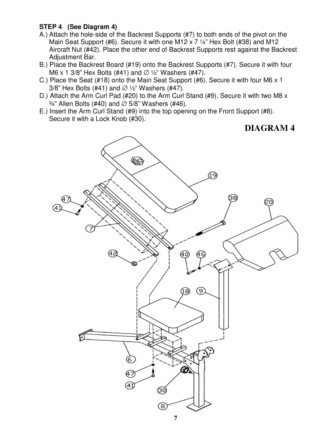
STEP 4 (See Diagram 4)
A.) Attach the
Main Seat Support (#6). Secure it with one M12 x 7 ¼” Hex Bolt (#38) and M12 Aircraft Nut (#42). Place the other end of Backrest Supports rest against the Backrest Adjustment Bar.
B.) Place the Backrest Board (#19) onto the Backrest Supports (#7). Secure it with four M6 x 1 3/8” Hex Bolts (#41) and ∅ ½” Washers (#47).
C.) Place the Seat (#18) onto the Main Seat Support (#6). Secure it with four M6 x 1 3/8” Hex Bolts (#41) and ∅ ½” Washers (#47).
D.) Attach the Arm Curl Pad (#20) to the Arm Curl Stand (#9). Secure it with two M8 x ¾” Allen Bolts (#40) and ∅ 5/8” Washers (#46).
E.) Insert the Arm Curl Stand (#9) into the top opening on the Front Support (#8). Secure it with a Lock Knob (#30).
DIAGRAM 4
7