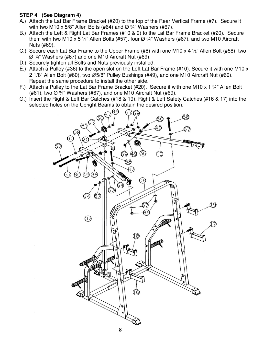
STEP 4 (See Diagram 4)
A.) Attach the Lat Bar Frame Bracket (#20) to the top of the Rear Vertical Frame (#7). Secure it with two M10 x 5/8” Allen Bolts (#64) and Ø ¾” Washers (#67).
B.) Attach the Left & Right Lat Bar Frames (#10 & 9) to the Lat Bar Frame Bracket (#20). Secure them with two M10 x 5 ¼” Allen Bolts (#57), four Ø ¾” Washers (#67), and two M10 Aircraft Nuts (#69).
C.) Secure each Lat Bar Frame to the Upper Frame (#8) with one M10 x 4 ½” Allen Bolt (#58), two
ؾ” Washers (#67) and one M10 Aircraft Nut (#69). D.) Securely tighten all Bolts and Nuts previously installed.
E.) Attach a Pulley (#36) to the open slot on the Left Lat Bar Frame (#10). Secure it with one M10 x 2 1/8” Allen Bolt (#60), two ∅ 5/8” Pulley Bushings (#49), and one M10 Aircraft Nut (#69). Repeat the same procedure to install the other side.
F.) Attach a Pulley to the Lat Bar Frame Bracket (#20). Secure it with one M10 x 1 ¾” Allen Bolt (#61), two Ø ¾” Washers (#67), and one M10 Aircraft Nut (#69).
G.) Insert the Right & Left Bar Catches (#18 & 19), Right & Left Safety Catches (#16 & 17) into the selected holes on the Upright Beams to obtain the desired position.
8