ASSEMBLY INSTRUCTION
Tools Required to Assemble the Machine: Two Adjustable Wrenches and Allen
Wrenches. NOTE: It is strongly recommended this machine to be assembled by two or more people to avoid possible injury.
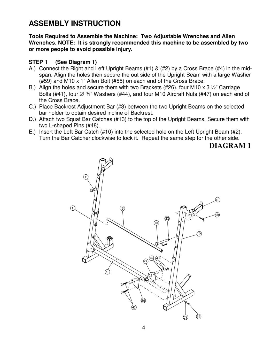
STEP 1 (See Diagram 1)
A.) Connect the Right and Left Upright Beams (#1) & (#2) by a Cross Brace (#4) in the mid- span. Align the holes then secure the out side of the Upright Beam with a large Washer (#59) and M10 x 1” Allen Bolt (#55) on each end of the Cross Brace.
B.) Align the holes and secure them with two Brackets (#26), four M10 x 3 ½” Carriage Bolts (#41), four ∅ ¾” Washers (#44), and four M10 Aircraft Nuts (#47) on each end of the Cross Brace.
C.) Place Backrest Adjustment Bar (#3) between the two Upright Beams on the selected bar holder to obtain desired incline of Backrest.
D.) Attach two Squat Bar Catches (#13) to the top of the Upright Beams. Secure them with two
E.) Insert the Left Bar Catch (#10) into the selected hole on the Left Upright Beam (#2). Turn the Bar Catcher clockwise to lock it. Repeat the same step for the other side.
DIAGRAM 1
4