STEP 2 (See Diagram 2)
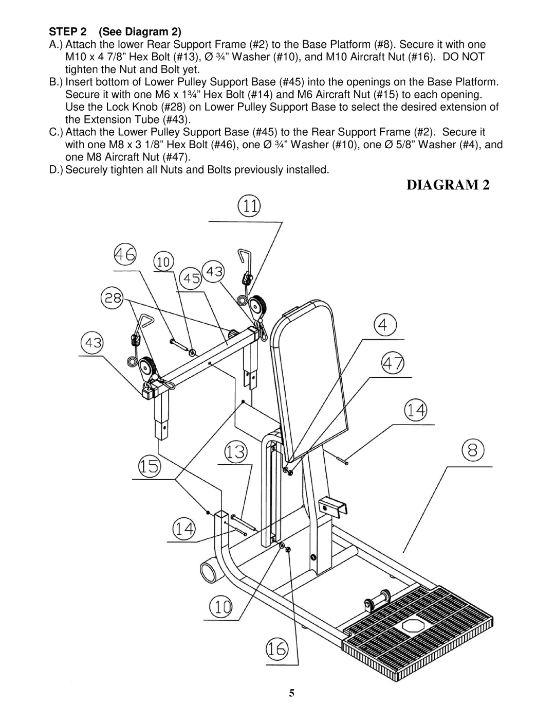
A.) Attach the lower Rear Support Frame (#2) to the Base Platform (#8). Secure it with one M10 x 4 7/8” Hex Bolt (#13), Ø ¾” Washer (#10), and M10 Aircraft Nut (#16). DO NOT tighten the Nut and Bolt yet.
B.) Insert bottom of Lower Pulley Support Base (#45) into the openings on the Base Platform.
Secure it with one M6 x 1¾” Hex Bolt (#14) and M6 Aircraft Nut (#15) to each opening. Use the Lock Knob (#28) on Lower Pulley Support Base to select the desired extension of the Extension Tube (#43).
C.) Attach the Lower Pulley Support Base (#45) to the Rear Support Frame (#2). Secure it with one M8 x 3 1/8” Hex Bolt (#46), one Ø ¾” Washer (#10), one Ø 5/8” Washer (#4), and one M8 Aircraft Nut (#47).
D.) Securely tighten all Nuts and Bolts previously installed.
DIAGRAM 2
5