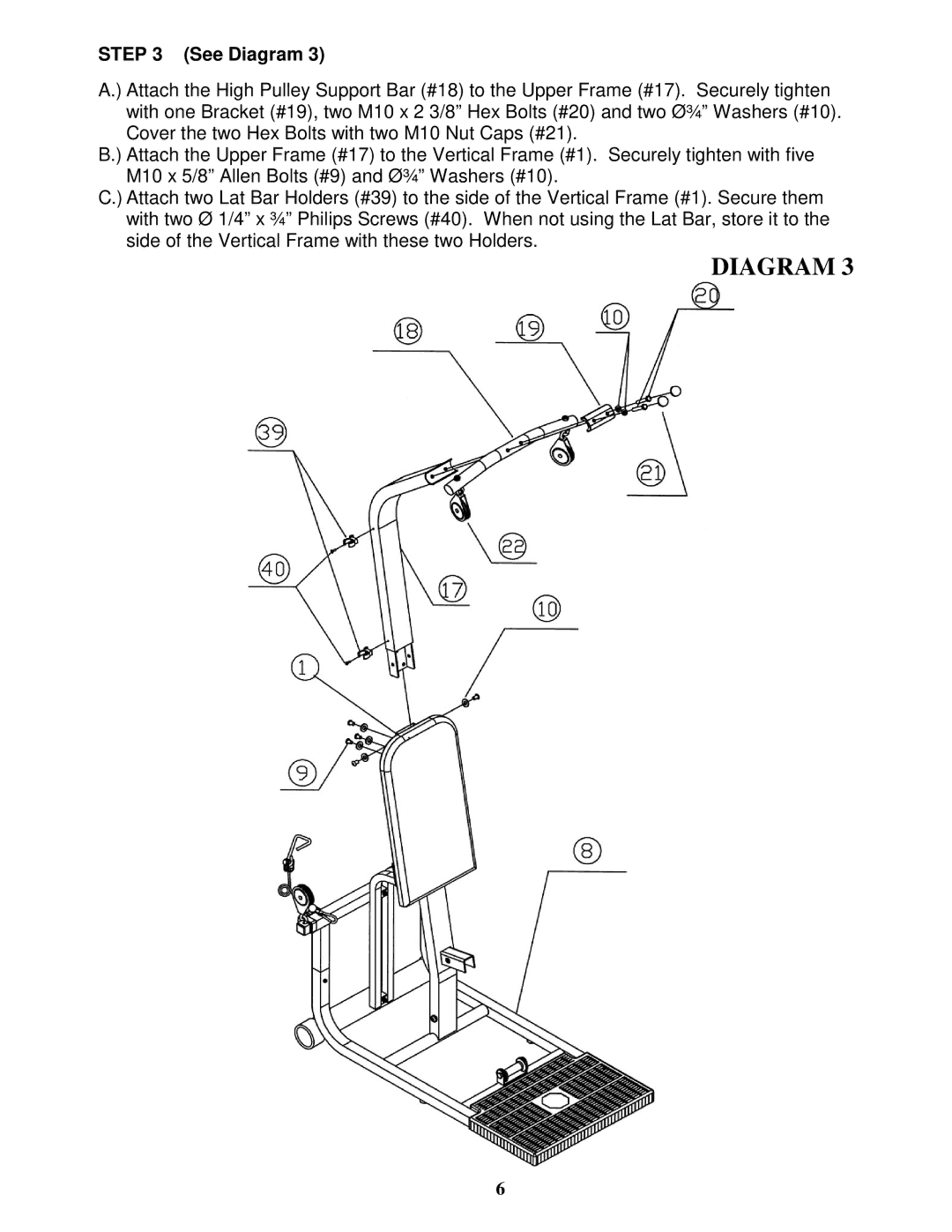
STEP 3 (See Diagram 3)
A.) Attach the High Pulley Support Bar (#18) to the Upper Frame (#17). Securely tighten with one Bracket (#19), two M10 x 2 3/8” Hex Bolts (#20) and two ؾ” Washers (#10). Cover the two Hex Bolts with two M10 Nut Caps (#21).
B.) Attach the Upper Frame (#17) to the Vertical Frame (#1). Securely tighten with five M10 x 5/8” Allen Bolts (#9) and ؾ” Washers (#10).
C.) Attach two Lat Bar Holders (#39) to the side of the Vertical Frame (#1). Secure them with two Ø 1/4” x ¾” Philips Screws (#40). When not using the Lat Bar, store it to the side of the Vertical Frame with these two Holders.
DIAGRAM 3
6