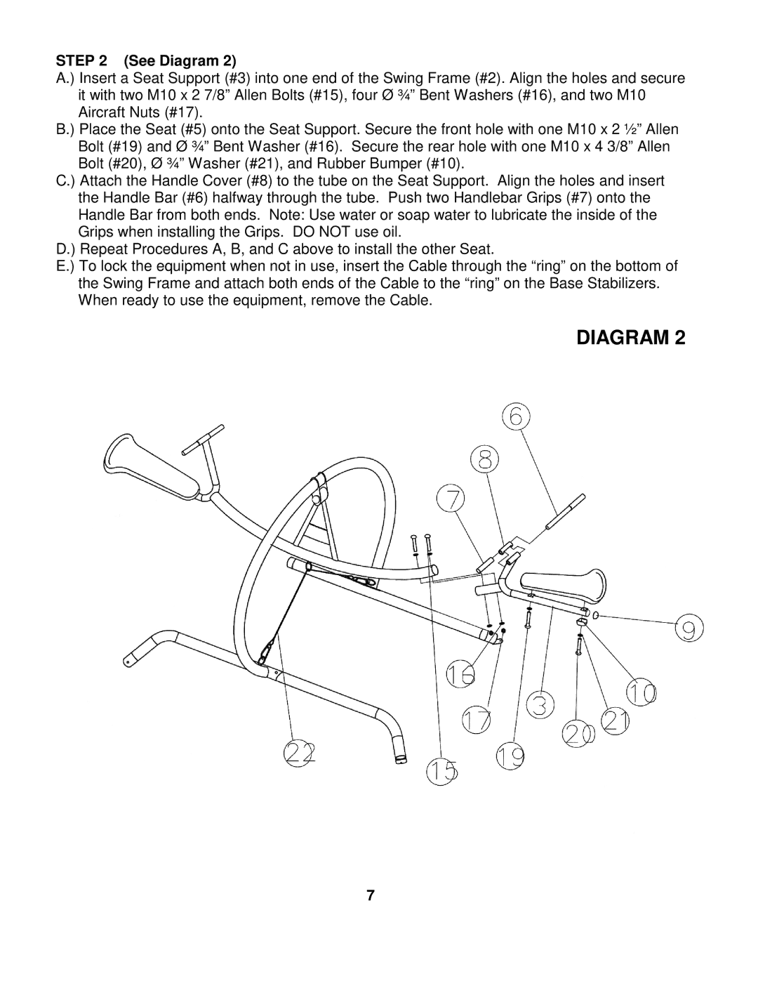
STEP 2 (See Diagram 2)
A.) Insert a Seat Support (#3) into one end of the Swing Frame (#2). Align the holes and secure it with two M10 x 2 7/8” Allen Bolts (#15), four Ø ¾” Bent Washers (#16), and two M10 Aircraft Nuts (#17).
B.) Place the Seat (#5) onto the Seat Support. Secure the front hole with one M10 x 2 ½” Allen Bolt (#19) and Ø ¾” Bent Washer (#16). Secure the rear hole with one M10 x 4 3/8” Allen Bolt (#20), Ø ¾” Washer (#21), and Rubber Bumper (#10).
C.) Attach the Handle Cover (#8) to the tube on the Seat Support. Align the holes and insert the Handle Bar (#6) halfway through the tube. Push two Handlebar Grips (#7) onto the Handle Bar from both ends. Note: Use water or soap water to lubricate the inside of the Grips when installing the Grips. DO NOT use oil.
D.) Repeat Procedures A, B, and C above to install the other Seat.
E.) To lock the equipment when not in use, insert the Cable through the “ring” on the bottom of the Swing Frame and attach both ends of the Cable to the “ring” on the Base Stabilizers. When ready to use the equipment, remove the Cable.
DIAGRAM 2
7
