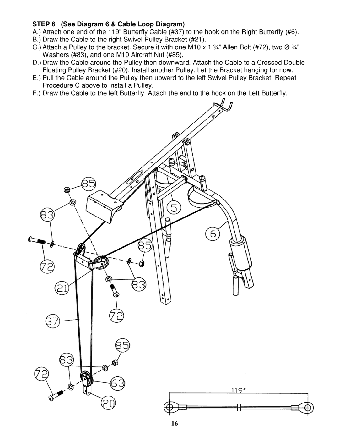
STEP 6 (See Diagram 6 & Cable Loop Diagram)
A.) Attach one end of the 119” Butterfly Cable (#37) to the hook on the Right Butterfly (#6). B.) Draw the Cable to the right Swivel Pulley Bracket (#21).
C.) Attach a Pulley to the bracket. Secure it with one M10 x 1 ¾” Allen Bolt (#72), two Ø ¾” Washers (#83), and one M10 Aircraft Nut (#85).
D.) Draw the Cable around the Pulley then downward. Attach the Cable to a Crossed Double Floating Pulley Bracket (#20). Install another Pulley. Let the Bracket hanging for now.
E.) Pull the Cable around the Pulley then upward to the left Swivel Pulley Bracket. Repeat Procedure C above to install a Pulley.
F.) Draw the Cable to the left Butterfly. Attach the end to the hook on the Left Butterfly.
16