ASSEMBLY INSTRUCTION
Tools required assembling the machine: Two Adjustable Wrenches and Allen Wrenches
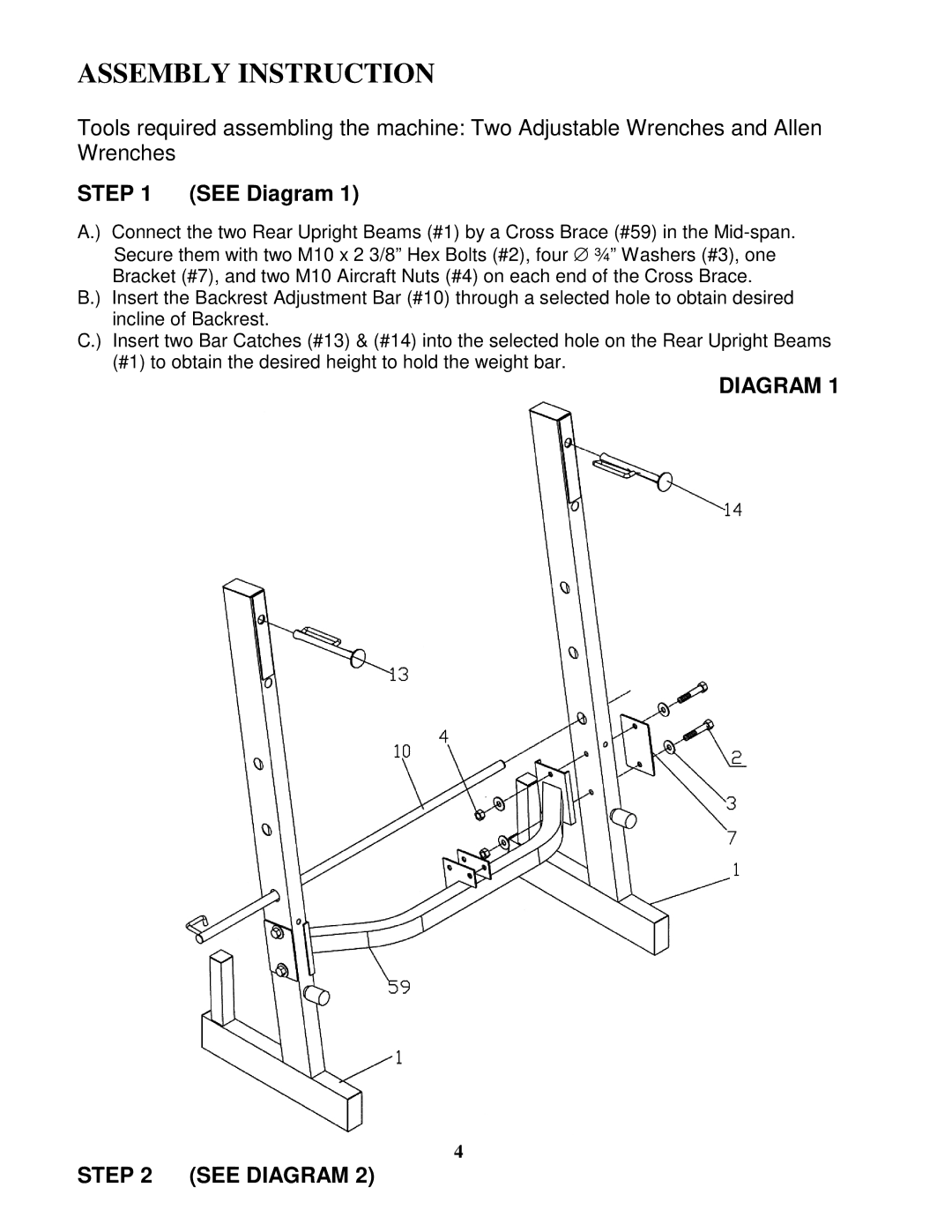
STEP 1 (SEE Diagram 1)
A.) Connect the two Rear Upright Beams (#1) by a Cross Brace (#59) in the
B.) Insert the Backrest Adjustment Bar (#10) through a selected hole to obtain desired incline of Backrest.
C.) Insert two Bar Catches (#13) & (#14) into the selected hole on the Rear Upright Beams (#1) to obtain the desired height to hold the weight bar.
DIAGRAM 1
4