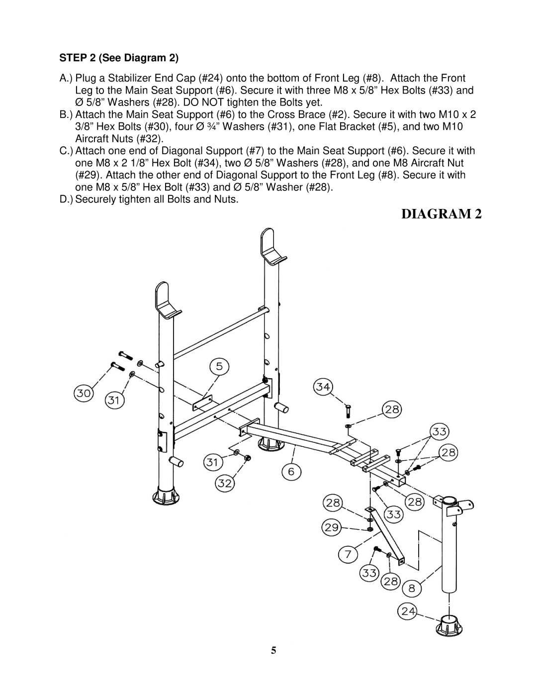
STEP 2 (See Diagram 2)
A.) Plug a Stabilizer End Cap (#24) onto the bottom of Front Leg (#8). Attach the Front Leg to the Main Seat Support (#6). Secure it with three M8 x 5/8” Hex Bolts (#33) and Ø 5/8” Washers (#28). DO NOT tighten the Bolts yet.
B.) Attach the Main Seat Support (#6) to the Cross Brace (#2). Secure it with two M10 x 2 3/8” Hex Bolts (#30), four Ø ¾” Washers (#31), one Flat Bracket (#5), and two M10 Aircraft Nuts (#32).
C.) Attach one end of Diagonal Support (#7) to the Main Seat Support (#6). Secure it with one M8 x 2 1/8” Hex Bolt (#34), two Ø 5/8” Washers (#28), and one M8 Aircraft Nut (#29). Attach the other end of Diagonal Support to the Front Leg (#8). Secure it with one M8 x 5/8” Hex Bolt (#33) and Ø 5/8” Washer (#28).
D.) Securely tighten all Bolts and Nuts.
DIAGRAM 2
5