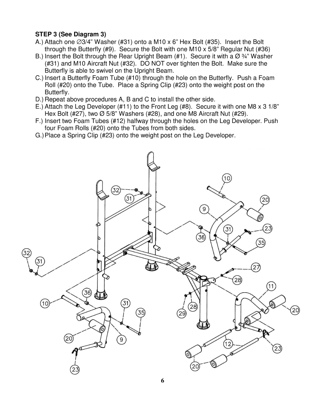
STEP 3 (See Diagram 3)
A.) Attach one ∅ 3/4” Washer (#31) onto a M10 x 6” Hex Bolt (#35). Insert the Bolt through the Butterfly (#9). Secure the Bolt with one M10 x 5/8” Regular Nut (#36)
B.) Insert the Bolt through the Rear Upright Beam (#1). Secure it with a Ø ¾” Washer (#31) and M10 Aircraft Nut (#32). DO NOT over tighten the Bolt. Make sure the Butterfly is able to swivel on the Upright Beam.
C.) Insert a Butterfly Foam Tube (#10) through the hole on the Butterfly. Push a Foam Roll (#20) onto the Tube. Place a Spring Clip (#23) onto the weight post on the Butterfly.
D.) Repeat above procedures A, B and C to install the other side.
E.) Attach the Leg Developer (#11) to the Front Leg (#8). Secure it with one M8 x 3 1/8” Hex Bolt (#27), two Ø 5/8” Washers (#28), and one M8 Aircraft Nut (#29).
F.) Insert two Foam Tubes (#12) halfway through the holes on the Leg Developer. Push four Foam Rolls (#20) onto the Tubes from both sides.
G.) Place a Spring Clip (#23) onto the weight post on the Leg Developer.
6