Electrical Connection
Your appliance is now supplied with a 13 amp fused plug that can be plugged into a 13 amp socket for immediate use. Before using the appliance please read the instructions below.
WARNING - THIS APPLIANCE MUST BE EARTHED. THE FOLLOWING OPERATIONS SHOULD BE CARRIED OUT BY A QUALIFIED ELECTRICIAN.
Replacing the fuse:
When replacing a faulty fuse, a 13 amp ASTA approved fuse to BS 1362 should always be used, and the fuse cover re- fitted. If the fuse cover is lost, the plug must not be used until a replacement is obtained.
Replacement fuse covers:
If a replacement fuse cover is fitted, it must be of the correct colour as indicated by the coloured marking or the colour that is embossed in words on the base of the plug. Replacements can be obtained directly from your nearest Service Depot.
Removing the plug:
If your appliance has a
-the plug is replaced by a fused 13 amp
or:
-the mains cable is wired directly into a 13 amp cable outlet, controlled by a switch, (in compliance with BS 5733) which is accessible without moving the appliance.
Please note: for appliances with a rating greater than 13
amp (eg: electric hob, double ovens and freestanding electric cookers etc.) the mains cable must be wired into a cooker output point with a rating of 45 amp. In this case the cable is not supplied.
Disposing of the plug:
Ensure that before disposing of the plug itself, you make the pins unusable so that it cannot be accidentally inserted into a socket.
Instructions for connecting cable to an alternative plug: Important: the wires in the mains lead are coloured in accordance with the following code:
Green & Yellow | - Earth |
Blue | - Neutral |
Brown | - Live |
As the colours of the wires in the mains lead may not correspond with the coloured markings identifying the terminals in your plug, proceed as follows:
Connect Green & Yellow wire to terminal marked "E" or or coloured Green or Green & Yellow.
Connect Brown wire to terminal marked "L" or coloured Red. Connect Blue wire to terminal marked "N" or coloured Black. If a 13 amp plug (BS 1363) is used it must be fitted with a 13 amp fuse. A 15 amp plug must be protected by a 15 amp fuse, either in the plug or adaptor or at the distribution board. If you are in any doubt about the electrical supply to your machine, consult a qualified electrician before use.
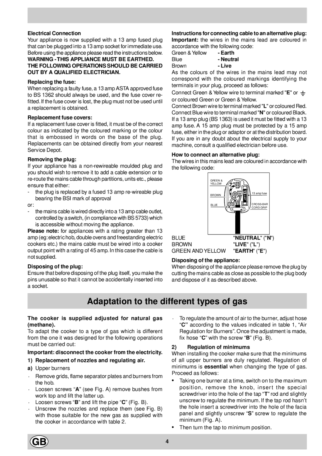
How to connect an alternative plug:
The wires in this mains lead are coloured in accordance with the following code:
GREEN &
YELLOW
BROWN | 13 amp fuse |
| |
BLUE | |
| CORD GRIP |
BLUE | "NEUTRAL" ("N") |
BROWN | "LIVE" ("L") |
GREEN AND YELLOW | "EARTH" ("E") |
Disposing of the appliance:
When disposing of the appliance please remove the plug by cutting the mains cable as close as possible to the plug body and dispose of it as described above.
Adaptation to the different types of gas
The cooker is supplied adjusted for natural gas (methane).
To adapt the cooker to a type of gas which is different from the one it was designed for the following operations must be carried out:
Important: disconnect the cooker from the electricity.
1)Replacement of nozzles and regulating air. a) Upper burners
·Remove grids, flame separator plates and burners from the hob.
·Loosen screws “A” (see Fig. A) remove bushes from work top and lift the latter up.
·Loosen screws “B” and lift the pipe “ C” (Fig. B).
·Unscrew the nozzles and replace them (see Fig. B) with those suitable for the new gas as supplied with the cooker in accordance with table 2.
·To regulate the amount of air to the burner, adjust hose “C” according to the values indicated in table 1, “Air Regulation for Burners”. Once the adjustment is made, fix hose “C” with the screw “ B” (Fig. B).
2)Regulation of minimums
When installing the cooker make sure that the minimums of all upper burners are duly regulated. Regulation of minimums is essential when changing the type of gas. Proceed as follows:
•Taking one burner at a time, switch on to the maximum position, remove the knob, insert the special screwdriver into the hole of the tap “T” rod and slightly unscrew to regulate the minimum. If the tap rod hasn’t the hole insert a screwdriver into the hole of the facia panel and slightly unscrew “S” screw to regulate the minimum (Fig. A).
•Then turn the tap to minimum position.
4