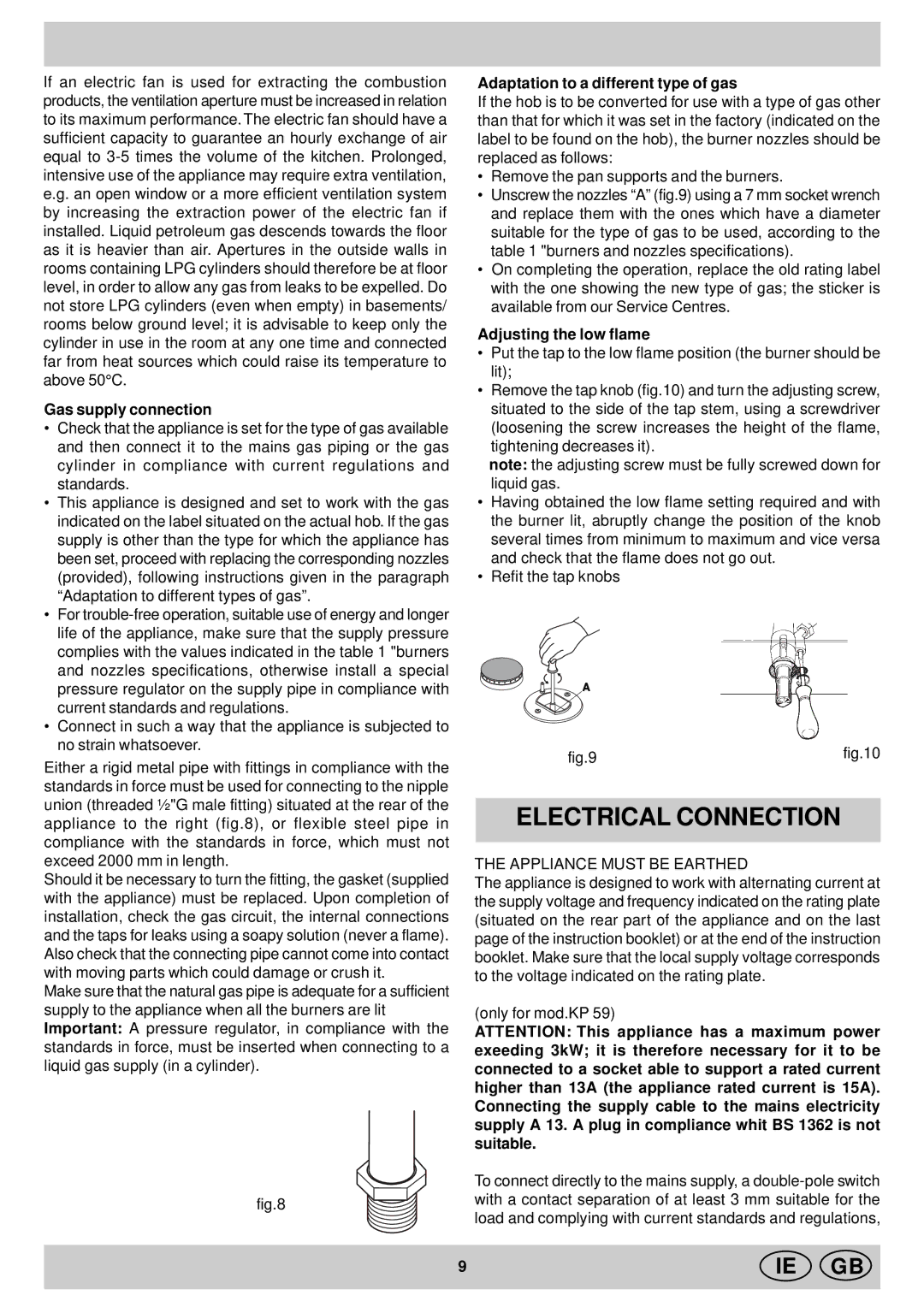
Indesit KP 9508 E (X)/G Electrical Connection, Gas supply connection, Adjusting the low flame

Models: KP 9508 E (X)/G KP 59 MS.C (X)/G KP 9508 E( X)/G

1 16
Download 16 pages 25.4 Kb
Page 11
Image 11
Gas supply connection

If an electric fan is used for extracting the combustion products, the ventilation aperture must be increased in relation to its maximum performance. The electric fan should have a sufficient capacity to guarantee an hourly exchange of air equal to 3-5 times the volume of the kitchen. Prolonged, intensive use of the appliance may require extra ventilation, e.g. an open window or a more efficient ventilation system by increasing the extraction power of the electric fan if installed. Liquid petroleum gas descends towards the floor as it is heavier than air. Apertures in the outside walls in rooms containing LPG cylinders should therefore be at floor level, in order to allow any gas from leaks to be expelled. Do not store LPG cylinders (even when empty) in basements/ rooms below ground level; it is advisable to keep only the cylinder in use in the room at any one time and connected far from heat sources which could raise its temperature to above 50°C.

Gas supply connection

Check that the appliance is set for the type of gas available and then connect it to the mains gas piping or the gas cylinder in compliance with current regulations and standards.

This appliance is designed and set to work with the gas indicated on the label situated on the actual hob. If the gas supply is other than the type for which the appliance has been set, proceed with replacing the corresponding nozzles (provided), following instructions given in the paragraph “Adaptation to different types of gas”.

For trouble-free operation, suitable use of energy and longer life of the appliance, make sure that the supply pressure complies with the values indicated in the table 1 "burners and nozzles specifications, otherwise install a special pressure regulator on the supply pipe in compliance with current standards and regulations.

Connect in such a way that the appliance is subjected to no strain whatsoever.

Either a rigid metal pipe with fittings in compliance with the standards in force must be used for connecting to the nipple union (threaded ½"G male fitting) situated at the rear of the appliance to the right (fig.8), or flexible steel pipe in compliance with the standards in force, which must not exceed 2000 mm in length.

Should it be necessary to turn the fitting, the gasket (supplied with the appliance) must be replaced. Upon completion of installation, check the gas circuit, the internal connections and the taps for leaks using a soapy solution (never a flame). Also check that the connecting pipe cannot come into contact with moving parts which could damage or crush it.

Make sure that the natural gas pipe is adequate for a sufficient supply to the appliance when all the burners are lit Important: A pressure regulator, in compliance with the standards in force, must be inserted when connecting to a liquid gas supply (in a cylinder).

Adaptation to a different type of gas

If the hob is to be converted for use with a type of gas other than that for which it was set in the factory (indicated on the label to be found on the hob), the burner nozzles should be replaced as follows:

Remove the pan supports and the burners.

Unscrew the nozzles “A” (fig.9) using a 7 mm socket wrench and replace them with the ones which have a diameter suitable for the type of gas to be used, according to the table 1 "burners and nozzles specifications).

On completing the operation, replace the old rating label with the one showing the new type of gas; the sticker is available from our Service Centres.

Adjusting the low flame

Put the tap to the low flame position (the burner should be lit);

Remove the tap knob (fig.10) and turn the adjusting screw, situated to the side of the tap stem, using a screwdriver (loosening the screw increases the height of the flame, tightening decreases it).

note: the adjusting screw must be fully screwed down for liquid gas.

Having obtained the low flame setting required and with the burner lit, abruptly change the position of the knob several times from minimum to maximum and vice versa and check that the flame does not go out.

Refit the tap knobs

A

fig.9

fig.10


ELECTRICAL CONNECTION

THE APPLIANCE MUST BE EARTHED

The appliance is designed to work with alternating current at the supply voltage and frequency indicated on the rating plate (situated on the rear part of the appliance and on the last page of the instruction booklet) or at the end of the instruction booklet. Make sure that the local supply voltage corresponds to the voltage indicated on the rating plate.

(only for mod.KP 59)

ATTENTION: This appliance has a maximum power exeeding 3kW; it is therefore necessary for it to be connected to a socket able to support a rated current higher than 13A (the appliance rated current is 15A). Connecting the supply cable to the mains electricity supply A 13. A plug in compliance whit BS 1362 is not suitable.

To connect directly to the mains supply, a double-pole switch

fig.8Adaptation to a different type of gas with a contact separation of at least 3 mm suitable for the load and complying with current standards and regulations,

9

IE GB

Page 11
Image 11
Indesit KP 9508 E (X)/G manual Electrical Connection, Gas supply connection, Adaptation to a different type of gas, Ie Gb