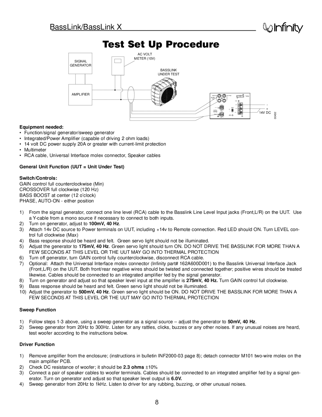
Bass Link specifications
The Infinity Bass Link is a powerful and innovative subwoofer system designed for automotive audio enthusiasts who demand deep, rich bass without compromising on space. This self-contained, compact unit is engineered to deliver high-quality low-frequency sounds, making it an ideal addition to any car audio setup.One of the standout features of the Infinity Bass Link is its unique, all-in-one design. The system integrates an amplifier and a subwoofer in a single enclosure, which not only saves space but also simplifies installation. This compact nature allows it to fit into a variety of locations within a vehicle, including behind the seats, under the cargo area, or in the trunk, providing versatility that many traditional subwoofer setups lack.
The Bass Link utilizes a powerful 10-inch subwoofer that is capable of delivering exceptional bass response. It is equipped with a built-in 200-watt RMS amplifier, ensuring that it produces deep and impactful sound while efficiently powering the subwoofer. This combination of high power and quality construction makes it suitable for a wide range of music genres, from hip-hop and electronic to rock and jazz.
Another notable characteristic of the Infinity Bass Link is its easy installation process. It comes with a comprehensive installation guide, and its intelligent design includes automatic gain control and a low-pass filter, which ensures seamless integration with factory or aftermarket audio systems. The system also features a remote bass control, allowing users to adjust the subwoofer level from the front of the vehicle, enhancing convenience.
Infinity’s commitment to quality is evident in the Bass Link’s build materials. The durable enclosure is constructed to withstand the rigors of automotive environments, while the premium components ensure long-lasting performance. Additionally, the Bass Link is engineered with a response range that complements the frequencies produced by standard speakers, providing a balanced overall sound.
In summary, the Infinity Bass Link is a smart choice for those looking to enhance their car's audio system with premium bass quality. Its compact design, powerful amplification, and ease of installation make it a standout option for car audio enthusiasts seeking impactful sound without sacrificing space. Whether you are a casual listener or an avid audiophile, the Infinity Bass Link provides an impressive auditory experience that is sure to elevate your driving soundtrack.

