GENERAL DESCRIPTION
ARO Systems are totally enclosed, sealing the material in the system from air and moisture, preventing premature
INSTALLATION
The 650299
When the following instructions are observed, heavy paste materials can be pumped directly from their original 55 gallon drum without air inclusion or excessive waste. The follower plate creates an air tight seal as well as
OPERATING INSTRUCTIONS
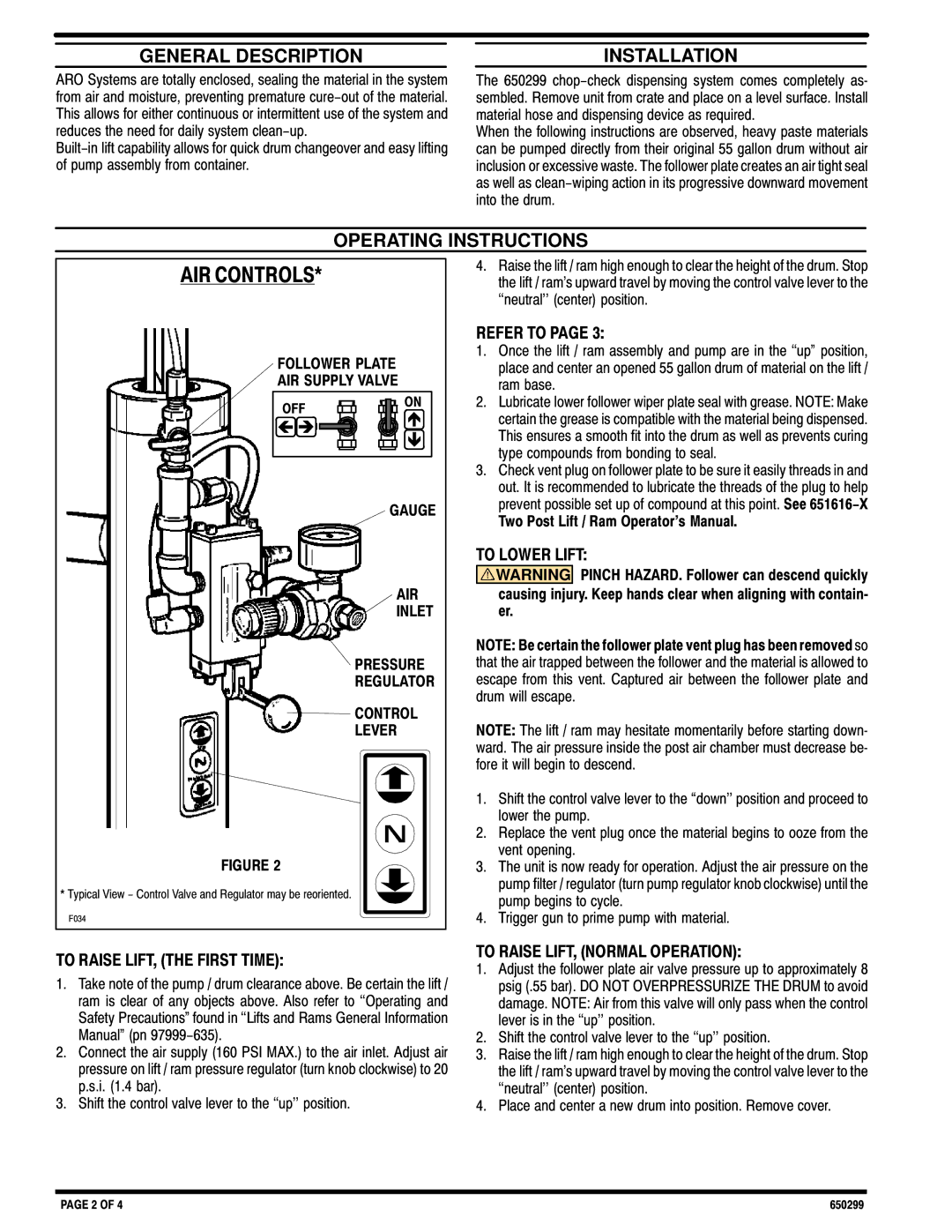
AIR CONTROLS*
FOLLOWER PLATE
AIR SUPPLY VALVE
OFF ![]()
![]()
![]()
![]()
![]() ON
ON
GAUGE
AIR
INLET
PRESSURE
REGULATOR
CONTROL
LEVER
FIGURE 2
* Typical View - Control Valve and Regulator may be reoriented.
F034
4.Raise the lift / ram high enough to clear the height of the drum. Stop the lift / ram's upward travel by moving the control valve lever to the ``neutral'' (center) position.
REFER TO PAGE 3:
1.Once the lift / ram assembly and pump are in the ``up" position, place and center an opened 55 gallon drum of material on the lift / ram base.
2.Lubricate lower follower wiper plate seal with grease. NOTE: Make certain the grease is compatible with the material being dispensed. This ensures a smooth fit into the drum as well as prevents curing type compounds from bonding to seal.
3.Check vent plug on follower plate to be sure it easily threads in and out. It is recommended to lubricate the threads of the plug to help prevent possible set up of compound at this point. See
TO LOWER LIFT:
![]()
![]() WARNING PINCH HAZARD. Follower can descend quickly causing injury. Keep hands clear when aligning with containB er.
WARNING PINCH HAZARD. Follower can descend quickly causing injury. Keep hands clear when aligning with containB er.
NOTE: Be certain the follower plate vent plug has been removed so that the air trapped between the follower and the material is allowed to escape from this vent. Captured air between the follower plate and drum will escape.
NOTE: The lift / ram may hesitate momentarily before starting downD ward. The air pressure inside the post air chamber must decrease beD fore it will begin to descend.
1.Shift the control valve lever to the ``down'' position and proceed to lower the pump.
2.Replace the vent plug once the material begins to ooze from the vent opening.
3.The unit is now ready for operation. Adjust the air pressure on the pump filter / regulator (turn pump regulator knob clockwise) until the pump begins to cycle.
4.Trigger gun to prime pump with material.
TO RAISE LIFT, (THE FIRST TIME):
1.Take note of the pump / drum clearance above. Be certain the lift / ram is clear of any objects above. Also refer to ``Operating and Safety Precautions" found in ``Lifts and Rams General Information Manual" (pn
2.Connect the air supply (160 PSI MAX.) to the air inlet. Adjust air pressure on lift / ram pressure regulator (turn knob clockwise) to 20 p.s.i. (1.4 bar).
3.Shift the control valve lever to the ``up'' position.
TO RAISE LIFT, (NORMAL OPERATION):
1.Adjust the follower plate air valve pressure up to approximately 8 psig (.55 bar). DO NOT OVERPRESSURIZE THE DRUM to avoid damage. NOTE: Air from this valve will only pass when the control lever is in the ``up'' position.
2.Shift the control valve lever to the ``up'' position.
3.Raise the lift / ram high enough to clear the height of the drum. Stop the lift / ram's upward travel by moving the control valve lever to the ``neutral'' (center) position.
4.Place and center a new drum into position. Remove cover.
PAGE 2 OF 4 | 650299 |