BREF Electric Fireplace
Screen Kit Installation
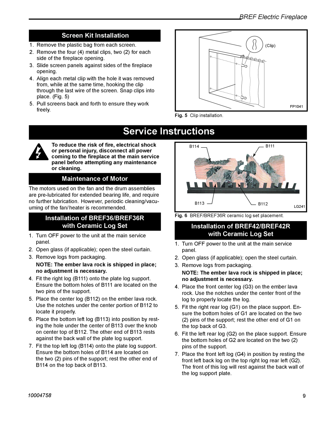
1.Remove the plastic bag from each screen.
2.Remove the four (4) metal clips, two (2) for each side of the fireplace opening.
3.Slide screen panels against sides of the fireplace opening.
4.Align each metal clip with the hole it was removed from, while at the same time, hooking the clip through the last wire of the screen. Snap clips into place. (Fig. 5)
5.Pull screens back and forth to ensure they work freely.
(Clip)
FP1041
Fig. 5 Clip installation.
Service Instructions
To reduce the risk of fire, electrical shock or personal injury, disconnect all power coming to the fireplace at the main service panel before attempting any maintenance or cleaning.
Maintenance of Motor
The motors used on the fan and the drum assemblies are
Installation of BREF36/BREF36R
with Ceramic Log Set
1.Turn OFF power to the unit at the main service panel.
2.Open glass (if applicable); open the steel curtain.
3.Remove logs from packaging.
NOTE: The ember lava rock is shipped in place; no adjustment is necessary.
4.Fit the right log (B111) onto the plate log support. Ensure the bottom holes of B111 are located on the two pins of the support.
5.Place the center log (B112) on the ember lava rock. Use the notches under the center portion of B112 to locate it properly.
6.Place the bottom left log (B113) into position by rest- ing the hole under the center of B113 over the knob on center top of B112. The other end of B113 rests against the back wall of the plate log support.
7.Fit the top left log (B114) onto the plate log support. Ensure the bottom holes of B114 are located on the two (2) pins of the support; rest the other end of B114 on the top back of B113.
| B114 | B111 |
|
| B113 | B112 | LG241 |
|
|
| |
Fig. 6 | BREF/BREF36R ceramic log set placement. |
| |
Installation of BREF42/BREF42R
with Ceramic Log Set
1.Turn OFF power to the unit at the main service panel.
2.Open glass (if applicable); open the steel curtain.
3.Remove logs from packaging.
NOTE: The ember lava rock is shipped in place; no adjustment is necessary.
4.Place the front center log (G3) on the ember lava rock. Use the notches under the center front of the log to properly locate the log.
5.Fit the right rear log (G1) on the place support. En- sure the bottom holes of G1 are located on the two
(2) pins of the support; rest the other end of G1 on the top back of G3.
6.Fit the left rear log (G2) on the place support. Ensure the bottom holes of G2 are located on the two (2) pins of the support.
7.Place the front left log (G4) in position by resting the front left back log on the top right log rear left (G2). The front of this log will rest against the back wall of the log support plate.
10004758 | 9 |