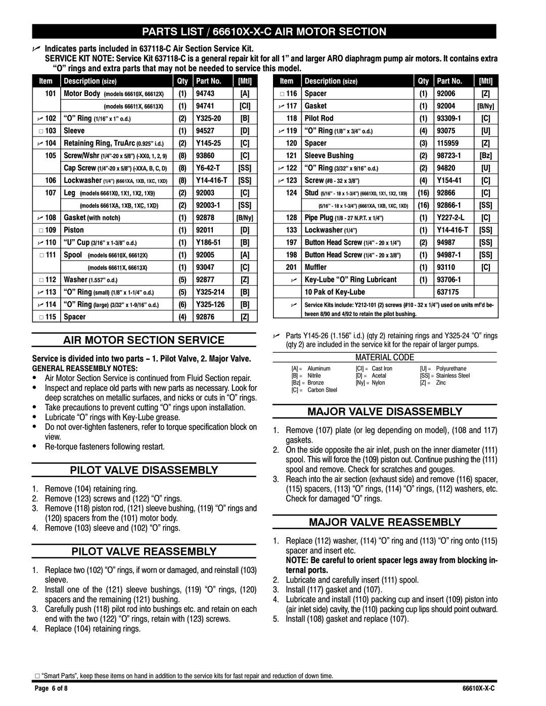
Ingersoll-Rand manual Parts List / 66610X-X-C AIR Motor Section

Models: 66610X-X-C

1 8
Download 8 pages 25.17 Kb
Page 6
Image 6

PARTS LIST / 66610X-X-C AIR MOTOR SECTION

nIndicates parts included in 637118-C Air Section Service Kit.

SERVICE KIT NOTE: Service Kit 637118-C is a general repair kit for all 1" and larger ARO diaphragm pump air motors. It contains extra rings and extra parts that may not be needed to service this model.

Item

Description (size)

Qty

Part No.

[Mtl]


101

Motor Body (models 66610X, 66612X)

(1)

94743

[A]


(models 66611X, 66613X)

(1)

94741

[CI]


n 102

(1/16" x 1" o.d.)

(2)

Y325-20

[B]


V 103

Sleeve

(1)

94527

[D]


n 104

Retaining Ring, TruArc (0.925" i.d.)

(2)

Y145-25

[C]


105

Screw/Wshr (1/4"-20 x 5/8") (-XX0, 1, 2, 9)

(8)

93860

[C]


Cap Screw (1/4"-20 x 5/8") (-XXA, B, C, D)

(8)

Y6-42-T

[SS]


106

Lockwasher (1/4") (6661XA, 1XB, 1XC, 1XD)

(8)

Y14-416-T

[SS]


107

Leg (models 6661X0, 1X1, 1X2, 1X9)

(2)

92003

[C]


(models 6661XA, 1XB, 1XC, 1XD)

(2)

92003-1

[SS]


n 108

Gasket (with notch)

(1)

92878

[B/Ny]


V 109

Piston

(1)

92011

[D]


n 110

(3/16" x 1-3/8" o.d.)

(1)

Y186-51

[B]


V 111

Spool (models 66610X, 66612X)

(1)

92005

[A]


(models 66611X, 66613X)

(1)

93047

[C]


V 112

Washer (1.557" o.d.)

(5)

92877

[Z]


n 113

(small) (1/8" x 1-1/4" o.d.)

(5)

Y325-214

[B]


n 114

(large) (3/32" x 1-9/16" o.d.)

(6)

Y325-126

[B]


V 115

Spacer

(4)

92876

[Z]

AIR MOTOR SECTION SERVICE

Service is divided into two parts − 1. Pilot Valve, 2. Major Valve.

GENERAL REASSEMBLY NOTES:

SAir Motor Section Service is continued from Fluid Section repair.

SInspect and replace old parts with new parts as necessary. Look for deep scratches on metallic surfaces, and nicks or cuts in

STake precautions to prevent cutting

SLubricate

SDo not over-tighten fasteners, refer to torque specification block on view.

SRe-torque fasteners following restart.

PILOT VALVE DISASSEMBLY

1.Remove (104) retaining ring.

2.Remove (123) screws and (122)

3.Remove (118) piston rod, (121) sleeve bushing, (119) (120) spacers from the (101) motor body.

4.Remove (103) sleeve and (102)

PILOT VALVE REASSEMBLY

1.Replace two (102) sleeve.

2.Install one of the (121) sleeve bushings, (119) spacers and the remaining (121) bushing.

3.Carefully push (118) pilot rod into bushings etc. and retain on each end with the two (122)

4.Replace (104) retaining rings.

Item

Description (size)

Qty

Part No.

[Mtl]


V 116

Spacer


(1)

92006

[Z]


n 117

Gasket


(1)

92004

[B/Ny]


118

Pilot Rod


(1)

93309-1

[C]


n 119

(1/8" x 3/4" o.d.)


(4)

93075

[U]


120

Spacer


(3)

115959

[Z]


121

Sleeve Bushing


(2)

98723-1

[Bz]


n 122

(3/32" x 9/16" o.d.)


(2)

94820

[U]


n 123

Screw (#8 - 32 x 3/8")


(4)

Y154-41

[C]


124

Stud (5/16" - 18 x 1-3/4") (6661X0, 1X1, 1X2, 1X9)


(16)

92866

[C]


(5/16" - 18 x 1-3/4") (6661XA, 1XB, 1XC, 1XD)


(16)

92866-1

[SS]


128

Pipe Plug (1/8 - 27 N.P.T. x 1/4")


(1)

Y227-2-L

[C]


133

Lockwasher (1/4")


(1)

Y14-416-T

[SS]


197

Button Head Screw (1/4" - 20 x 1/4")


(2)

94987

[SS]


198

Button Head Screw (1/4" - 20 x 3/8")


(1)

94987-1

[SS]


201

Muffler


(1)

93110

[C]


n

Key-Lube


(1)

93706-1


10 Pak of Key-Lube


637175


n

Service Kits include: Y212-101 (2) screws (#10 - 32 x 1/4") used on units mf’d be-


tween 8/90 and 4/92 to retain the pilot bushing.


nParts Y145-26 (1.156" i.d.) (qty 2) retaining rings and Y325-24 (qty 2) are included in the service kit for the repair of larger pumps.

MATERIAL CODE

[A] =

Aluminum

[CI] =

Cast Iron

[U] =

Polyurethane

[B] =

Nitrile

[D] =

Acetal

[SS] = Stainless Steel

[Bz] =

Bronze

[Ny] =

Nylon

[Z] =

Zinc

[C] =

Carbon Steel


MAJOR VALVE DISASSEMBLY

1.Remove (107) plate (or leg depending on model), (108 and 117) gaskets.

2.On the side opposite the air inlet, push on the inner diameter (111) spool. This will force the (109) piston out. Continue pushing the (111) spool and remove. Check for scratches and gouges.

3.Reach into the air section (exhaust side) and remove (116) spacer, (115) spacers, (113) 14) 12) washers, etc.

Check for damaged

MAJOR VALVE REASSEMBLY

1.Replace (112) washer, (114) 13) 15) spacer and insert etc.

NOTE: Be careful to orient spacer legs away from blocking in- ternal ports.

2.Lubricate and carefully insert (111) spool.

3.Install (117) gasket and (107).

4.Lubricate and install (110) packing cup and insert (109) piston into (air inlet side) cavity, the (110) packing cup lips should point outward.

5.Install (108) gasket and replace (107).

V

Page 6 of 8

66610X-X-C

Page 6
Image 6
Ingersoll-Rand manual Parts List / 66610X-X-C AIR Motor Section

66610X-X-C specifications

The Ingersoll-Rand 66610X-X-C is a robust, high-performance air compressor that has gained traction across various industries due to its reliability and efficiency. This particular model stands out in terms of versatility and is widely used in manufacturing, construction, and automotive applications.

One of the main features of the Ingersoll-Rand 66610X-X-C is its powerful motor, which offers impressive output while maintaining energy efficiency. The compressor is designed to deliver high-flow performance, ensuring that it meets the demands of various pneumatic tools and equipment. An integrated air dryer is also a standard feature, which helps to eliminate moisture from the compressed air, prolonging the lifespan of tools and improving overall efficiency.

The 66610X-X-C utilizes advanced technology to optimize its operational performance. With its variable speed drive, the compressor can adjust its output based on the demand, saving energy and reducing operational costs. This feature also helps in minimizing wear and tear on the unit, resulting in lower maintenance needs over its lifespan.

In terms of design, the Ingersoll-Rand 66610X-X-C boasts a compact and portable structure, making it easy to transport and move around job sites. Its rugged construction ensures it can withstand harsh working environments and demanding applications. The compressor is also equipped with a user-friendly control panel that allows for easy monitoring and adjustments, enhancing the overall user experience.

Safety features are prominent in the design of the 66610X-X-C. The unit is fitted with automatic shut-off capabilities and pressure relief valves to prevent damage from excessive pressure levels. Additionally, it is designed to operate at lower noise levels, making it suitable for use in more noise-sensitive environments, ensuring a safer and more comfortable working atmosphere.

Another commendable characteristic of the Ingersoll-Rand 66610X-X-C is its low maintenance requirements. Thanks to its durable construction and reliable components, users can expect longer intervals between service needs, which contributes to cost savings in the long run.

In conclusion, the Ingersoll-Rand 66610X-X-C is a feature-rich air compressor that combines power, efficiency, and reliability. Its advanced technologies and robust construction make it a valuable asset for various industrial applications, catering to both high demand and precision needs. Whether for construction or manufacturing, this model exemplifies what modern air compressors should aspire to be, standing as a testament to Ingersoll-Rand’s commitment to innovation and quality in the field of compressed air solutions.