AIR AND LUBE REQUIREMENTS
![]()
![]() WARNING EXCESSIVE AIR PRESSURE. Can cause pump damage, personal injury or property damage.
WARNING EXCESSIVE AIR PRESSURE. Can cause pump damage, personal injury or property damage.
SA filter capable of filtering out particles larger than 50 microns should be used on the air supply. There is no lubrication required other than the “O” ring lubricant which is applied during assembly or repair.
SIf lubricated air is present, make sure that is compatible with the Ni- trile “O” rings in the air motor section of the pump.
OPERATING INSTRUCTIONS
SAlways flush the pump with a solvent compatible with the material being pumped if the material being pumped is subject to ‘‘setting up” when not in use for a period of time.
SDisconnect the air supply from the pump if it is to be inactive for a few hours.
SThe outlet material volume is governed not only by the air supply but also by the material supply available at the inlet. The material supply tubing should not be too small or restrictive. Be sure not to use hose which might collapse.
SWhen the diaphragm pump is used in a
SSecure the diaphragm pump legs to a suitable surface to insure against damage by vibration.
MAINTENANCE
Refer to the part views and descriptions as provided on page 4 through 7 for parts identification and Service Kit information.
SCertain ARO “Smart Parts” are indicated which should be available for fast repair and reduction of down time.
SService kits are divided to service two separate diaphragm pump functions: 1. AIR SECTION, 2. FLUID SECTION. The FLUID SEC- TION is divided further to match typical part MATERIAL OPTIONS.
SProvide a clean work surface to protect sensitive internal moving parts from contamination from dirt and foreign matter during service disassembly and reassembly.
MAINTENANCE CONTINUED
SKeep good records of service activity and include pump in preven- tive maintenance program.
SBefore disassembling empty captured material in the outlet manifold by turning the pump upside down to drain material from the pump.
FLUID SECTION DISASSEMBLY
1.Remove top manifold(s).
2.Remove (22) balls, (19 and 33) “O” rings and (21) seats.
3.Remove (15) fluid caps.
NOTE: Only PTFE diaphragm models use a (7) primary diaphragm and an (8) backup diaphragm. Refer to the auxiliary view in the Fluid Section illustration.
4.Remove the (6) nut, (7) or (7 / 8) diaphragms and (5) washers.
5.Remove (3 and 4) “O” rings.
NOTE: Do not scratch or mar the surface of (1) diaphragm rod.
FLUID SECTION REASSEMBLY
SReassemble in reverse order.
SClean and inspect all parts. Replace worn or damaged parts with new parts as required.
SLubricate (1) diaphragm rod and (2) “O” ring with
SUse ARO PN /
SBe certain (7) or (7 / 8) diaphragm(s) align properly with (15) fluid caps before making final torque adjustments on bolt and nuts to avoid twisting the diaphragm.
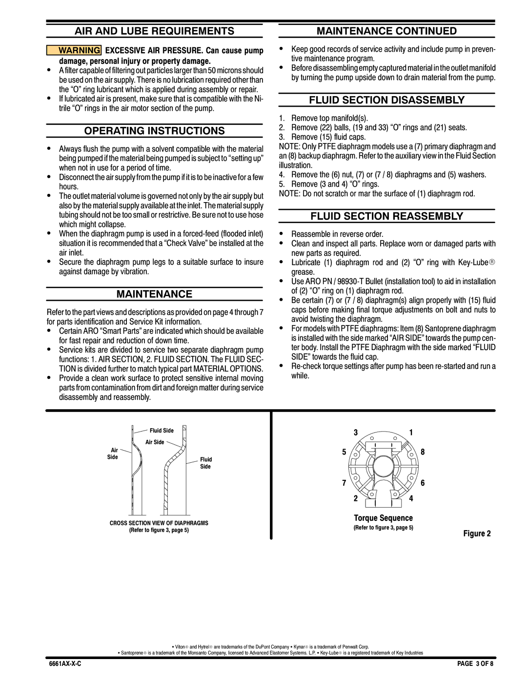
SFor models with PTFE diaphragms: Item (8) Santoprene diaphragm is installed with the side marked “AIR SIDE” towards the pump cen- ter body. Install the PTFE Diaphragm with the side marked “FLUID SIDE” towards the fluid cap.
S
Fluid Side
Air Side ![]()
31
Air
Side
Fluid Side
58
76
24
CROSS SECTION VIEW OF DIAPHRAGMS
(Refer to figure 3, page 5)
Torque Sequence
(Refer to figure 3, page 5)
Figure 2
S VitonR and HytrelR are trademarks of the DuPont Company S KynarR is a trademark of Penwalt Corp.
S SantopreneR is a trademark of the Monsanto Company, licensed to Advanced Elastomer Systems. L.P. S
PAGE 3 OF 8 |