FEED RATE CONTROL VALVES

REMOTE OPERATION

lTurnvalve (23), marked“R”an top of housing,approximately1-1/2 turns counterclockwise (open).

lTurn the other valve (23), marked “F”on top of housing, clock- wise until closed (do not tighten too snugly).

lStartunit and slowly turn valve (23) marked“F”counterclockwise

(open) until the desired forward rate of feed IS reached.

lA final adjustmentof the rate of return (retract) can be made with the valve (23) marked “R”on housing.

MANUAL OPERATION

install button bleed valve (25) in either the “F”port located at top of valve housing or the “F”port located at the rear of valve hous- ing. NOTE:Unused port must be plugged with pipe plug (24).

Depress button bleed valve (25) marked “F”on valve housing. The unit will start in the forward (advancing) mode and continue to feed forward until the adjusting screw “B”has depressedbleed valve (25) marked “R”to retract the unit. See set-up procedure. A manual emergency retract button bleed valve (25) can be in- stalled in “R”port at top of valve housing if desired. This valve con be usedto immediately retract the unit in case of misaligned part or other emergency. Valve not furnished.

Install a pressurebleed valve-ARO port number 9600 - in valve port marked “F”at either the top or rear of valve housing Connect pressure bleed valve - using 1/8” i.d. tubing - to o remote operated valve which, when actuated, feeds air pressure to the pressurebleed valve. Pressurebleed valve will bleed the air from “F”port of valve housing causing spool valve in housing to shift to the forward feed position thus starting the forward stroke of the unit.

Install a pressurebleed valve-ARO port number 9600 - in valve port marked “R”at the TOPof the valve housing and connect - using 1/8” i.d. tubing - to o remote MANUALLYoperated valve. This valve is used OSon emergency retract in case of a port mis- alignment or such only as the unit, when properly set-up and ap- plied, will automatically retract and return to the start position. See set-up procedure.

Refer to page 11for plumbing and schematic diagrams.

SPECIALNOTE:The air inlet and remote ports of valve housing hove tapered pipe threads and should not require the use of thread sealants, such as sealant tape or pipe joint compounds. Thread sealants when used improperly can contaminate air passages and cause valve or unit to malfunction.

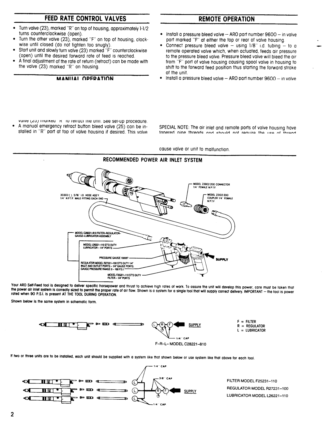
RECOMMENDEDPOWER AIR INLET SYSTEM

Your AROSelf-Feedtool is designed to deliver specific horsepower and thrust to achieve high rates of work. To assure the unit will develop this power care must be taken that the power air inlet system is correctly sized to permit the proper rote of air flow. Shown is a systemtar o single tool that will supply correct delivery. IMPORTANT-the tool ISpower rated when 90 P.S.I.is present AT THETOOLDURINGOPERATION.

Shown below Is the same system In schematic form.

F = FILTER

R = REGULATOR

L = LUBRICATOR

F-R-L- MODEL C28221-810

Iftwo or three units are to be installed, each unit should be supplied with o system like that shown below or use system like that above far each tool.

FILTER MODEL F25231-110

REGULATOR MODEL R27231-100

LUBRlCATOR MODEL L26221-110

Page 2
Image 2
Ingersoll-Rand 8248-B( )-( ) specifications Feed Rate Control Valves, Manual Operation, Remote Operation

8248-B( )-( ) specifications

The Ingersoll-Rand 8248-B air compressor represents a robust solution in the realm of industrial air systems, tailored to meet various demanding requirements across multiple sectors. This model is renowned for its efficiency, reliability, and versatility, making it an essential tool for a wide array of applications, from manufacturing and construction to automotive and maintenance tasks.

One of the main features of the Ingersoll-Rand 8248-B is its powerful motor, designed to deliver consistent air output while minimizing energy consumption. The compressor is equipped with a high-performance rotary screw design, which provides continuous air flow and reduces pulsation. This technology ensures that operators enjoy stable air pressure, optimizing the performance of air-powered tools and processes.

The 8248-B also boasts a compact and rugged construction, making it suitable for both stationary and portable applications. Its durable materials are engineered to withstand harsh operating conditions, ensuring longevity and reducing maintenance costs over time. This robustness is complemented by an efficient cooling system that prevents overheating, thereby prolonging the life of the compressor.

Another significant advantage of the Ingersoll-Rand 8248-B is its advanced control system, which incorporates user-friendly interfaces and smart technology. This system allows for real-time monitoring of performance metrics, enabling operators to make timely decisions and adjustments to enhance efficiency. Additionally, the compressor is designed with safety in mind, featuring automatic shut-off mechanisms and pressure relief valves that provide essential protection for users and the equipment.

The Ingersoll-Rand 8248-B air compressor is highly versatile, with customizable configurations that allow it to adapt to specific job site needs. Various options for tank size, motor power, and additional features such as sound enclosures can be integrated based on user requirements. Furthermore, the compressor's compatibility with a wide range of attachments and accessories makes it an ideal choice for those who require flexibility in their operations.

In summary, the Ingersoll-Rand 8248-B air compressor is a reliable and efficient solution for industrial air needs. With its powerful motor, robust design, advanced control system, and adaptability, this compressor stands out as an essential asset for businesses looking to enhance productivity and performance in their operations.