GENERAL DESCRIPTION AND OPERATION
The ARO model 8315 air operated marking pen is a high frequen- cy tool (approximately 36,000 c.p.m.) used for marking various hardened tool steels, other metals, plastics, glass, etc. It can be used as you would a pen or pencil.
The model 8315 features a turn type throttle, which should be turned to full on position (approximately one full turn
MAINTENANCE
Air tools are made of precision parts and should be handled with reasonable care when servicing. Excessive pressure exerted by a holding device may cause distortion of a part. Apply pressure evenly when disassembling (or assembling) parts which have a press fit. It is important that the correct tools and fixtures are used when servicing this air tool.
Disassembly should be done on a clean work bench with a clean cloth spread to prevent the loss of small parts. After disassembly is completed, all parts should be thoroughly washed in a clean sol- vent, blown dry with air and inspected for wear levels, abuse and contamination.
Before reassembling, lubricate pads where required. Use “0” ring lube 36460 for “0” ring assembly. When assembling “0” rings or parts adjacent “0” rings, care must be exercised to prevent dam- age to the rubber sealing surfaces.
When ordering pans, be sure to list part number, description, tool model number and serial number.
DISASSEMBLY AND ASSEMBLY
Disconnect air supply from tool or shut off air supply and drain line of compressed air before changing needle or otherwise perform- ing maintenance or service to tool.
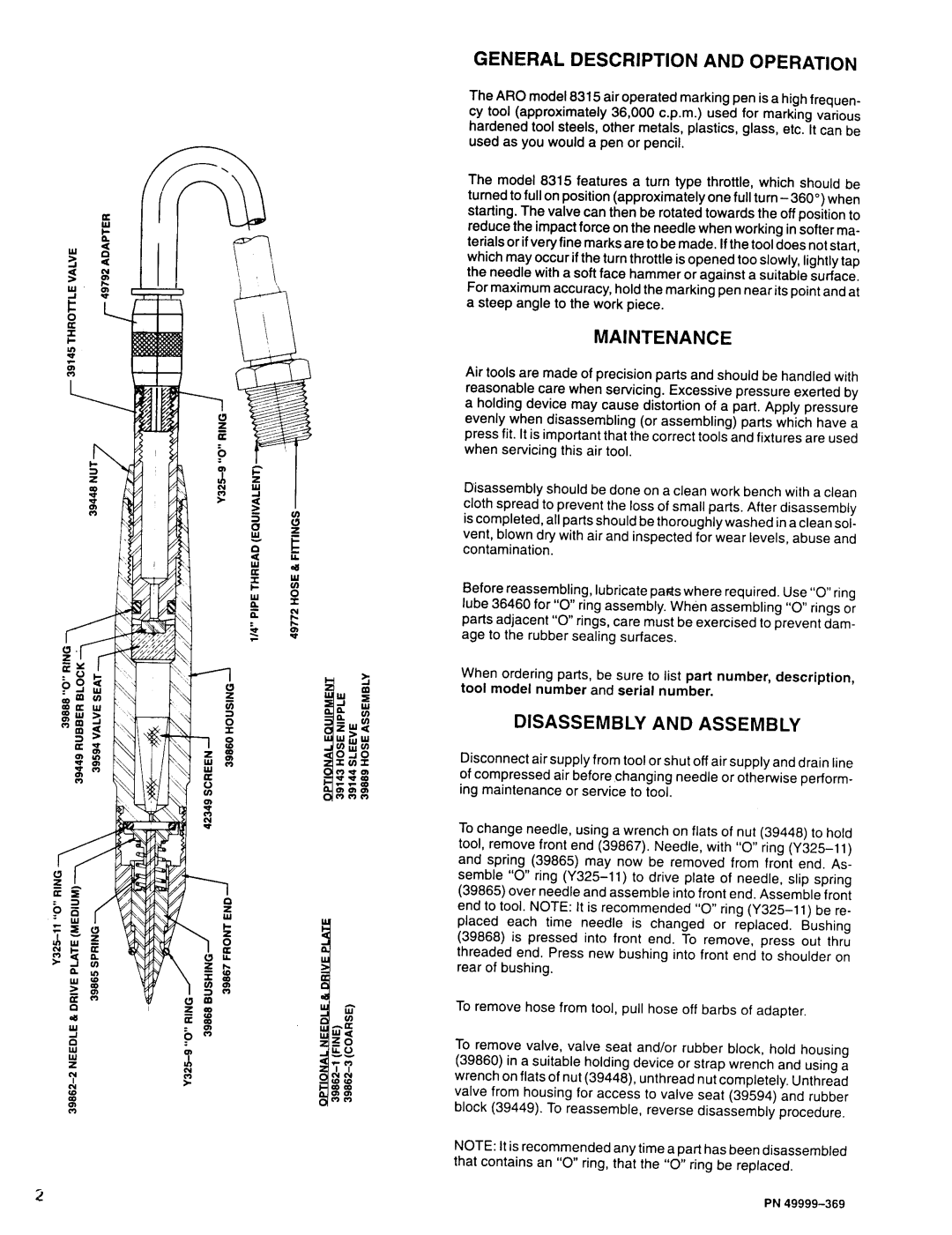
To change needle, using a wrench on flats of nut (39448) to hold tool, remove front end (39867). Needle, with “0” ring
To remove hose from tool, pull hose off barbs of adapter.
To remove valve, valve seat and/or rubber block, hold housing (39860) in a suitable holding device or strap wrench and using a wrench on flats of nut (39448), unthread nut completely. Unthread valve from housing for access to valve seat (39594) and rubber block (39449). To reassemble, reverse disassembly procedure.
NOTE: It is recommended any time a part has been disassembled that contains an “0” ring, that the “0” ring be replaced.
PN