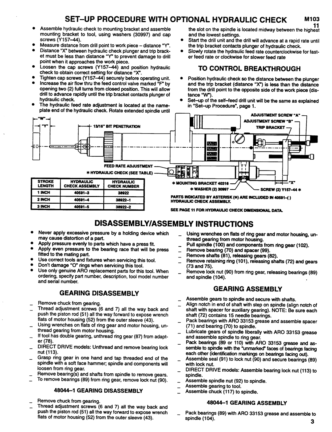
SET-UP PROCEDURE WITH OPTIONAL HYDRAULIC CHECK M103

11

Assemble

hydraulic check to mounting bracket and assemble


the slot on the spindle is located midway between the highest

mounting

bracket to tool, using washers (30997) and cap


and the lowest settings.

screws (Y157-44).

l Start the drill unit and the drill will advance at a rapid rate until

Measure distance from drill point to work piece - distance “Y".


the trip bracket contacts plunger of hydraulic check.

Distance “X”between hydraulic check plunger and trip brack-

l

Slowly rotate the hydraulic feed rate counterclockwise for fast-

et must be less than distance “Y"to prevent damage to drill


er feed rate or clockwise for slower feed rate

point when it approaches the work piece.


TO CONTROL BREAKTHROUGH

Loosen the cap screws (Y15744) and position hydraulic


check to obtain correct setting for distance “X”.


Position hydraulic check so the distance between the plunger

Tighten cap screws (Y157-44) securely before operating unit.

l

Increase the air flow thru the feed control valve marked “F"by


and the trip bracket (distance "X”) is less than the distance

opening two (2) full turns from closed position. This will allow


from the drill point to the opposite side of the work piece (dis-

drill to advance rapidly until the trip bracket contacts plunger of


tance "W").

hydraulic check.

l

The hydraulic feed rate adjustment is located at the name-


plate end of the hydraulic check. Rotate extended spindle until


FEED BATE ADJUSTMENT

SEE PAGE 11 FOB HYDRAULIC CHECK DIMENSIONAL DATA.

DISASSEMBLY/ASSEMBLY INSTRUCTIONS

l

l

l

Never apply excessive pressure by a holding device which may cause distortion of a part.

Apply pressure evenly to parts which have a press fit. Apply even pressure to the bearing race that will be press fitted to the mating part.

Use correct tools and fixtures when servicing this tool. Don’t damage “0”rings when servicing this tool.

Use only genuine ARO replacement parts for this tool. When ordering, specify part number, description, tool model number and serial number.

Using wrenches on flats of ring gear and motor housing, un- thread gearing from motor housing.

Pull spindle (100) and components from ring gear (102). Remove bearing (70) and spacer (99).

Remove shafts (81). releasing gears (82).

Remove retaining ring (101), releasing shafts (72) and gears (73 and 75).

Remove lock nut (90) from ring gear, releasing bearings (89) and spindle (104).

GEARING

DISASSEMBLY

GEARING ASSEMBLY

Assemble gears to spindle and secure with shafts.

Remove chuck from gearing.

Align notch in end of shaft with step on spindle (align notch of

Thread adjustment screws (6 and 7) all the way back and

shaft with spacer for auxiliary gearing). NOTE: Be sure each

push the piston rod (51) all the way forward to expose wrench

shaft (72) contains

15 needle bearings.

flats of motor housing (52) from the outer sleeve (43).

Pack bearings with ARO 33153 grease and assemble spacer

Using wrenches on flats of ring gear and motor housing, un-

(71) and bearing (70) to spindle.

thread gearing from motor housing.

Lubricate gears of spindle liberally with ARO 33153 grease

If tool has double gearing, unthread ring gear (87) from adapt-

and assemble spindle to ring gear.

er (78).


- Pack bearings (89 or 110) with ARO 33153 grease and as-

DIRECT DRIVE models: Unthread and remove bearing lock

semble to spindle with the ‘unmarked” faces of bearings facing

nut (113).


each other (identification markings on beatings facing out).

Grasp ring gear in one

hand and tap threaded end of the

Assemble seal (91) to lock nut (90) and secure bearings (89)

spindle with a soft face hammer; spindle and components will

with lock nut.


loosen from ring gear.


DIRECT DRIVE models: Assemble bearing lock nut (113) to

Remove bearing(s) and shafts from spindle to remove gears.

spindle.


To remove bearings (89) from ring gear, remove lock nut (90).

Assemble spindle

nut (92) to spindle.


Assemble gearing

to tool.

48044-1 GEARING DISASSEMBLY

Assemble chuck (117) to spindle.

Remove chuck from gearing.

48044-1 GEARING ASSEMBLY

Thread adjustment screws (6 and 7) all the way back and


push the piston rod (51) all the way forward to expose wrench

Pack bearings (89) with ARO 33153 grease and assemble to

flats of motor housing (52) from the outer sleeve (43).

spindle (104).

3


Page 3
Image 3
Ingersoll-Rand 8255-A, 8355A SET-UP Procedure with Optional Hydraulic Check M103, DISASSEMBLY/ASSEMBLY Instructions

8355A, 8255-A specifications

Ingersoll-Rand is a renowned name in the field of industrial manufacturing, particularly known for its production of air compressors and related equipment. Among its notable offerings are the Ingersoll-Rand 8255-A and 8355A pneumatic compressors, which exemplify robust engineering and cutting-edge technology. These models are tailored for demanding applications, providing the reliability and performance that professionals in various industries require.

One of the standout features of the Ingersoll-Rand 8255-A and 8355A is their powerful performance capability. Both models are designed to deliver a high CFM (Cubic Feet per Minute) output, ensuring adequate airflow for even the most demanding tools and pneumatic devices. This makes them suitable for a range of applications, from automotive repair and manufacturing processes to construction and heavy-duty maintenance tasks.

The compressors are equipped with advanced rotary screw technology, known for its efficiency and silent operation. This technology enables the compressors to generate compressed air continuously, with less energy consumption than traditional piston compressors. The durability of the rotary screw design reduces wear and tear, leading to longer lifespans and lower maintenance costs.

Another significant feature is the inclusion of a sophisticated control system. This system allows users to monitor and adjust various parameters, such as pressure and temperature, enhancing operational efficiency. Additionally, the user-friendly interface simplifies the task of managing the compressor, ensuring that it can be operated with minimal training.

The 8255-A and 8355A models also prioritize safety and environmental considerations. They come with built-in safety features that prevent overloading and ensure stable operations, protecting both the equipment and the user. Furthermore, their environmentally friendly design aligns with contemporary sustainability goals, making them a responsible choice for modern enterprises.

In terms of mobility, both compressors are designed for ease of transport. They feature rugged frames and wheels, enabling them to be moved easily across job sites. This portability enhances their versatility, allowing for quick relocation as jobs change in scope and location.

In conclusion, the Ingersoll-Rand 8255-A and 8355A compressors stand out because of their powerful performance, innovative technologies, and essential safety features. They represent a blend of reliability and efficiency, making them invaluable assets in a variety of industrial and commercial applications.