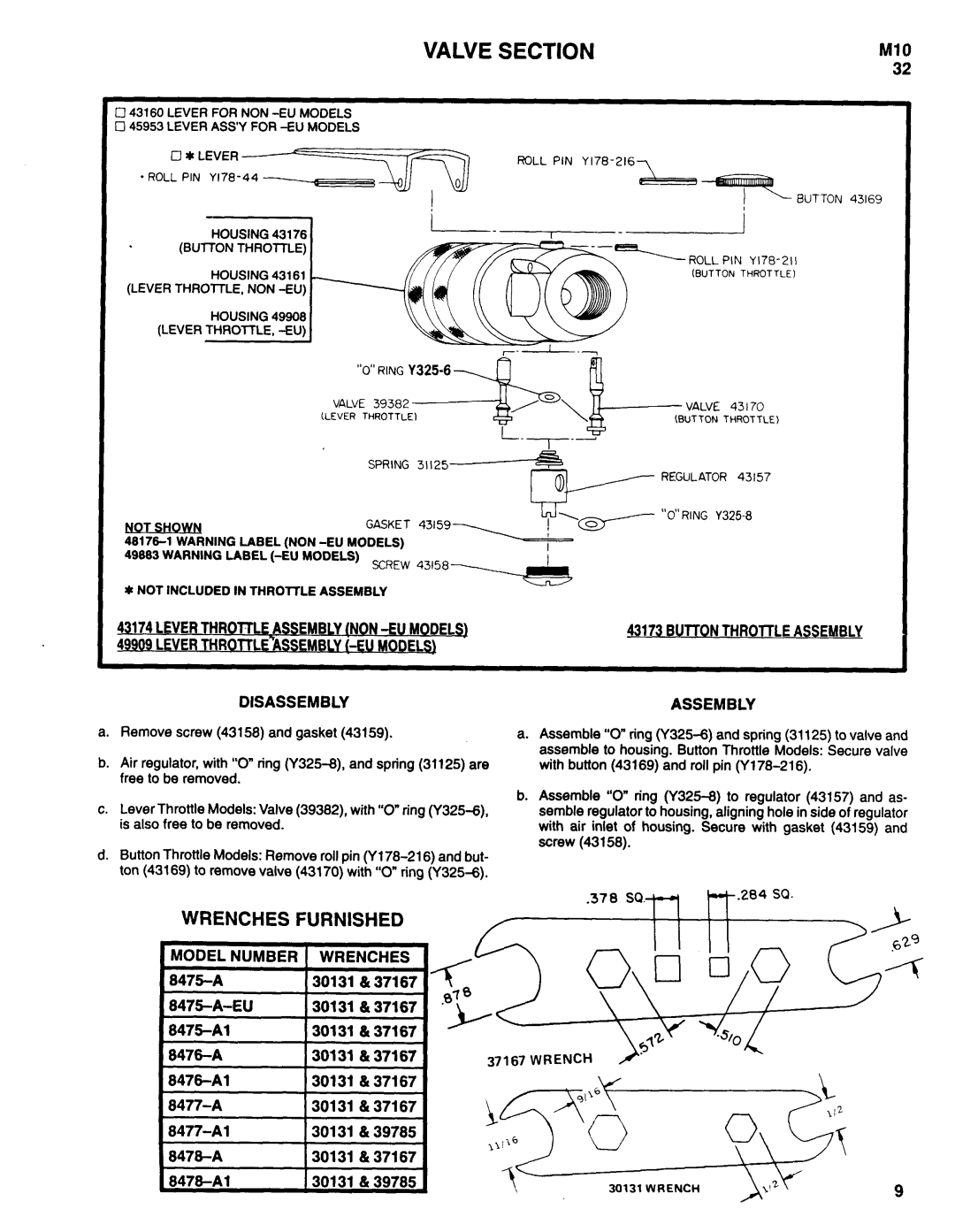
8477-A, 8478-A1, 8477-A1, 8475-A-( ), 8478-A specifications
Ingersoll-Rand is a renowned brand in the manufacturing of high-quality air compressors, tools, and related equipment. Among its extensive range of products, the models 8476-A, 8476-A1, 8475-A1, 8478-A, and 8475-A-( ) stand out for their performance and reliability. These models are designed for industrial applications, providing solutions for a variety of tasks in construction, automotive, and manufacturing industries.One of the key features of these models is their robust construction. Built with durable materials, they can withstand demanding conditions and are engineered for longevity. Their design incorporates advanced technology that enhances their performance while reducing maintenance needs. This reliability is crucial for businesses that depend on uninterrupted operations.
The 8476-A and 8476-A1 models are recognized for their high-efficiency air delivery systems, allowing for optimal airflow and minimizing energy consumption. This not only lowers operational costs but also aligns with the growing demand for energy-efficient machinery in industrial settings. Similarly, the 8475-A1 and 8478-A models are equipped with features that enable them to deliver consistent air pressure, which is essential for tools that require a steady supply of compressed air.
In terms of control technology, these compressors feature smart systems that optimize performance based on real-time conditions. This allows users to achieve the best results while extending the equipment's lifecycle. Additionally, the noise-reduction technology implemented in these models means they operate quietly, making them suitable for both indoor and outdoor applications.
With their versatile design, these compressors can be used in a range of settings. The models incorporate user-friendly controls that simplify operation, making them accessible to technicians of all skill levels. They are also equipped with a variety of output options to accommodate different tools and equipment, enhancing their applicability in various tasks.
Performance characteristics such as high PSI ratings and CFM outputs distinguish these models in the market. The 8475-A-( ) model, in particular, is notable for its ability to tackle the most challenging tasks, combining power and efficiency seamlessly.
In conclusion, Ingersoll-Rand’s 8476-A, 8476-A1, 8475-A1, 8478-A, and 8475-A-( ) models are designed to meet the rigorous demands of industrial applications. With their advanced features, durability, and efficiency, they provide reliable solutions that enhance productivity and reduce operational costs. For professionals seeking quality and performance, these models are exceptional choices that continue to uphold the brand's legacy of excellence.

